Energy Quotient Developer Documentation
Welcome to the Energy Quotient developer documentation. This guide covers technical integration, API usage, and development resources for EQ products.
Products
EQ Wave™ - Power quality sensor platform
- Technical specifications and architecture
- Firmware development
- System monitoring and integration
EQ Syntropy™ - Analytics and gateway platform
- Server architecture and deployment
- API integration
- CPOW (Continuous Point-on-Wave) data processing
- Enhancement proposals and planning
Getting Started
Support
For developer support: dev@eq.systems
© 2026 EQ Systems Inc.
EQ Wave: Energy Intelligence & Power Quality Sensor
The EQ Wave spans the entire energy-power quality spectrum, delivering breakthrough technology at one-fourth the cost of traditional solutions. Through continuous point-on-wave monitoring and real-time processing, it enables precise power quality analysis, sophisticated power control, and intelligent energy management—all from the same hardware platform, with software configuration determining the focus of each deployment.
Product Positioning
The EQ Wave operates on a continuous spectrum from energy management to power quality analysis:
-
Energy Management (left side of spectrum):
- Focused on cost reduction and sustainability
- Optimizing usage patterns and demand response
- Long-term analytics and planning
- Applications in building systems, renewable generation, and battery systems
-
Power Controls (middle of spectrum):
- Balancing energy efficiency and quality of service
- Real-time monitoring and control capabilities
- Applications in electric utilities, rail & transit, and DoD facilities
-
Power Quality Analysis (right side of spectrum):
- Protecting expensive equipment and sensitive processes
- High-precision monitoring and rapid response
- Applications in data centers, semiconductor manufacturing, and medical imaging
The hardware foundation is consistent across this spectrum, with software configuration determining where on the spectrum each deployment is focused. When referring to the “controller” aspect of the EQ Wave, we’re encompassing both the energy management (left) and power controls (middle) portions of the spectrum—collectively representing the “energy controller” functionality. The “analyzer” aspect refers primarily to the power quality analysis (right) portion of the spectrum.
EQ Syntropy™ enhances capabilities at all points on the spectrum through additional computational power, enabling deeper analysis and intelligence that goes beyond what the hardware’s onboard FPGA can provide alone.
Key Features
-
Advanced Data Acquisition:
- 32 kHz sampling at 24-bit resolution for “instant slow-motion replay”
- Complete 3-phase voltage and 4-channel current monitoring
- Sub-cycle response capabilities
- Patent-pending technology for high-precision analysis
-
Enterprise-Grade Design:
- True measurement isolation through fiber optics and digital barriers
- Industrial temperature range (-40 to +70°C)
- Robust enclosure options (polycarbonate or aluminum)
- Universal power input (85–528V AC, 5–36V DC, or USB)
- Compact industrial form factor (140 × 89 × 41 mm)
-
Real-time Processing:
- Dual high-performance network services
- Power monitoring with 10/12 cycle updates
- Continuous waveform streaming at 2ms intervals
- Deterministic performance for control applications
- Gap-less data recording capability
- Low-latency ½ cycle reporting
- Dual high-performance network services
Technical Specifications
Core Components
- Power Quality IC: ADE9430 with 24-bit, 32 kHz, 7-channel simultaneous sampling
- Processor: ARM Cortex-M4 based MCU (LPC4078FBD100) with floating point unit
- Memory: 512KB Flash, 64KB RAM, 32KB Peripheral RAM
- Networking: 100 Mbps fiber optic (100Base-FX) with PTP support
- Flexible Inputs: Support for both CT and Rogowski coil sensors
Data Services
- Power Monitoring (PMon): Aggregated metrics on TCP port 1535
- Continuous Waveform (CPOW): Raw waveform data on TCP port 1534
- Low Latency: < 2 ms data acquisition system
Complete Facility Solution
When integrated with EQ Syntropy™, the sensor enables capabilities across the entire energy-PQ spectrum:
Energy Management
- Demand Optimization:
- Load profiling and forecasting
- Peak demand management
- Energy cost reduction
- Energy Storage Control:
- Battery charge/discharge optimization
- Renewable integration
- Load balancing
Power Controls and PQ Monitoring
- Power System Protection:
- Threshold-based alerting
- Historical trend analysis
- Remote monitoring
- Power Control & Stabilization:
- Voltage regulation
- Critical load protection
- Surge/sag mitigation
- Harmonic Mitigation:
- Active/passive filtering
- Line reactor implementation
- Facility-wide protection
- Power Factor Correction:
- Capacitor bank control
- Load scheduling optimization
- Utility penalty avoidance
Advanced Power Quality (PQ) Analysis
- AI-powered anomaly detection
- Root cause analysis
- Predictive maintenance
- Equipment-specific analysis
- Sub-cycle event detection
Applications
The EQ Wave adapts to various positions on the energy-PQ spectrum, making it ideal for:
- Semiconductor Fabrication: Enhanced yield through precise power quality monitoring
- Medical Imaging: Reliable equipment validation and calibration
- Data Centers: Proactive power management and uptime protection
- Industrial Processes: Real-time control and quality optimization
- Energy Systems: Cost reduction through intelligent optimization
- Grid Infrastructure: Reliable integration of distributed resources
Integration Options
The EQ Wave integrates with the EQ Syntropy™ platform to provide enhanced capabilities at all points on the energy-PQ spectrum:
- Extended data storage and analytics
- AI-driven pattern recognition
- Predictive maintenance
- Energy optimization
- Advanced control applications
- Enterprise system connectivity
For detailed information, please refer to:
- Technical Specifications - Complete hardware specifications and architecture
- User Guide - Installation, configuration, and operation instructions
- Production Guide - Manufacturing and quality control procedures
© 2026 EQ Systems Inc.
Developer Information
For complete technical specifications including hardware components, schematics, and detailed architecture, see Technical Specifications.
Development Environment
Required Tools
- IDE: MCUXpresso IDE v11.8.0 or later
- Debug Probe: PEMicro USB Multilink Universal (USB-ML-UNIVERSAL)
- Alternative: USB-ML-UNIVERSAL-FX (faster but more expensive)
- Toolchain: ARM GCC (included with MCUXpresso)
Getting Started
- Install MCUXpresso IDE
- Import the EQ Wave project
- Connect debug probe to Tag-Connect interface
- Build and flash firmware
Code Organization
src/- Main application codedrivers/- Hardware drivers (ADE9430, DP83848, etc.)freertos/- FreeRTOS kernel and configurationlwip/- TCP/IP stackconfig/- Board and application configuration
Debug Configuration
- SWD interface via Tag-Connect
- Debug features available through conditional compilation
- Note: Full debug mode may impact real-time performance
Firmware Development Notes
Current Limitations
- Small CPOW buffer (< 10 ms) due to MCU RAM constraints
- Debug features introduce latency affecting concurrent data acquisition
- Random number generation needs improvement
Network Services
- Port 1535: Power monitor metrics (pmon)
- Port 1534: Continuous point-on-wave data (pwave)
Future Development
- Modbus TCP server implementation
- MQTT publisher for cloud integration
- PTP support for precision time synchronization
- GNSS timestamp integration
- Zenoh server for edge computing
- Runtime query engine (patent pending)
- Over-the-network firmware updates
- EEPROM-based configuration storage
Contributing
Please refer to the development guidelines and coding standards before submitting changes.
Support
For development support, contact: support@eq.systems
© 2026 EQ Systems Inc.
Monitoring and Diagnostics Guide
note
This guide covers ongoing monitoring, system health diagnostics, and performance optimization for the EQ Wave device.
System Health Monitoring
Status Indicators
LED Indicators:
- Power (Green): Solid when powered correctly
- Network (Amber): Flashing during network activity
- Status (Blue):
- Solid: All systems nominal
- Flashing: System errors or warnings
- Off: System fault
Real-Time Health Checks
System Performance:
- CPU utilization per task
- Memory usage and availability
- Network throughput and errors
- Temperature and thermal status
Data Quality Indicators:
- Sample rate consistency
- Data buffer status
- Network packet loss
- Timestamp accuracy
Hardware Status:
- Power supply voltage levels
- Internal temperature readings
- Network link status
- ADC performance metrics
System Diagnostics Access
Access diagnostics via TCP data streams and system monitoring port (1535)
Memory Usage Monitoring
Heap Utilization:
- Current usage percentage
- Peak usage tracking
- Available memory
- Memory fragmentation
Stack Usage:
- Per-task stack consumption
- Stack overflow detection
- High water mark tracking
- Task performance correlation
Buffer Management:
- Data buffer utilization
- Buffer overflow detection
- Queue depths
- Data loss indicators
Task Performance Monitoring
Real-Time Metrics:
- CPU utilization per task
- Task execution times
- Interrupt service routine performance
- Real-time constraint violations
Watchdog Status:
- Watchdog timer status
- Task responsiveness
- System hang detection
- Recovery mechanisms
Scheduling Statistics:
- Task scheduling latency
- Priority inversion detection
- Resource contention
- Load balancing effectiveness
Network Statistics
Connection Health:
- Active connections count
- Connection establishment rate
- Connection timeout events
- Data transmission rates
Packet Statistics:
- Packets transmitted/received
- Packet loss rates
- Error rates by type
- Retransmission statistics
Bandwidth Utilization:
- Current throughput
- Peak bandwidth usage
- Available bandwidth
- Network congestion indicators
Performance Optimization
Data Streaming Optimization
Waveform Data (Port 1534):
- Monitor for packet loss
- Optimize TCP buffer sizes
- Check network bandwidth utilization
- Verify client processing capacity
Power Monitoring (Port 1535):
- Check update rate consistency
- Monitor data accuracy
- Verify calculation performance
- Track processing latency
Network Performance Tuning
TCP Settings:
- Window size optimization
- Nagle algorithm configuration
- Keep-alive settings
- Timeout adjustments
Buffer Management:
- Increase buffer sizes for high-load applications
- Implement flow control
- Monitor queue depths
- Optimize memory allocation
System Performance Monitoring
CPU Load Management:
- Monitor task CPU usage
- Identify performance bottlenecks
- Optimize task priorities
- Load balance processing
Memory Optimization:
- Monitor memory fragmentation
- Optimize buffer allocation
- Implement memory pooling
- Track memory leaks
Error Logging and Analysis
System Error Categories
Hardware Errors:
- ADC conversion errors
- Power supply anomalies
- Temperature threshold violations
- Network interface errors
Software Errors:
- Task execution failures
- Memory allocation failures
- Protocol violations
- Configuration errors
Network Errors:
- Connection timeouts
- Data transmission errors
- Protocol synchronization issues
- Bandwidth limitations
Error Log Analysis
Log File Structure:
- Timestamp (UTC)
- Error severity level
- Error category
- Detailed error description
- System state information
Common Error Patterns:
- Intermittent network issues
- Memory usage trends
- Temperature cycling effects
- Power quality correlation
Diagnostic Data Collection
System Snapshots:
- Complete system state capture
- Configuration backup
- Performance metrics
- Error history
Event Logging:
- Configuration changes
- Network events
- Measurement anomalies
- User interactions
Preventive Maintenance Monitoring
Health Trending
Long-Term Monitoring:
- Performance degradation trends
- Error rate increases
- Resource utilization growth
- Environmental impact tracking
Predictive Indicators:
- Memory usage growth patterns
- Network performance decline
- Temperature trend analysis
- Hardware aging indicators
Automated Health Checks
Scheduled Diagnostics:
- Daily system health reports
- Weekly performance summaries
- Monthly trend analysis
- Quarterly maintenance recommendations
Alert Thresholds:
- Memory usage warnings
- Temperature alarm levels
- Network performance degradation
- Error rate increases
Remote Monitoring Capabilities
Cloud Integration
EQ Platform Monitoring:
- Centralized device monitoring
- Fleet-wide analytics
- Predictive maintenance
- Remote diagnostics
Third-Party Integration:
- SCADA system connectivity
- Building management systems
- Enterprise monitoring platforms
- Custom monitoring solutions
VPN and Remote Access
Secure Remote Monitoring:
- WireGuard VPN access
- Encrypted data transmission
- Remote diagnostic capabilities
- Secure configuration updates
Mobile Monitoring:
- Mobile device access
- Push notifications
- GPS location tracking
- Field technician tools
Data Quality Monitoring
Measurement Validation
Accuracy Verification:
- Compare readings to known references
- Monitor measurement consistency
- Track calibration drift
- Verify phase relationships
Data Integrity Checks:
- Check data completeness
- Verify timestamp accuracy
- Monitor sample rate stability
- Detect data corruption
Signal Quality Assessment
Input Signal Monitoring:
- Signal-to-noise ratio
- Input range utilization
- Clipping detection
- Harmonic content analysis
Environmental Impact:
- Temperature effect monitoring
- EMI/RFI interference detection
- Vibration impact assessment
- Humidity correlation analysis
Alarm and Notification System
Configurable Alarms
System Alarms:
- High temperature warnings
- Memory usage thresholds
- Network connectivity loss
- Power supply anomalies
Measurement Alarms:
- Voltage/current out of range
- Frequency deviations
- Power quality events
- Harmonic distortion limits
Notification Methods
Local Notifications:
- LED status indicators
- Web interface alerts
- Audible alarms (if configured)
- Display messages
Remote Notifications:
- Email alerts
- SNMP traps
- Syslog messages
- Mobile push notifications
Troubleshooting Common Issues
Performance Degradation
Symptoms:
- Slow web interface response
- Delayed data updates
- Network timeouts
- Missing data packets
Diagnostic Steps:
- Check system resource utilization
- Monitor network performance
- Review error logs
- Verify configuration settings
Data Quality Issues
Symptoms:
- Inconsistent measurements
- Noisy signals
- Missing data points
- Timestamp errors
Diagnostic Steps:
- Verify measurement connections
- Check environmental conditions
- Monitor signal quality
- Compare with reference measurements
Network Connectivity Problems
Symptoms:
- Cannot connect to device
- Intermittent data loss
- Slow data transmission
- Connection timeouts
Diagnostic Steps:
- Test basic network connectivity
- Check fiber optic connections
- Monitor network statistics
- Verify network configuration
Maintenance Monitoring
Routine Health Checks
Daily Monitoring:
- System status verification
- Error log review
- Performance metrics check
- Data quality assessment
Weekly Analysis:
- Trend analysis
- Performance comparisons
- Error pattern identification
- Resource usage review
Monthly Reports:
- Comprehensive system health
- Performance trending
- Maintenance recommendations
- Optimization opportunities
Firmware and Software Updates
Update Monitoring:
- Check for firmware updates
- Monitor update success
- Verify post-update functionality
- Document changes and improvements
Rollback Procedures:
- Backup current configuration
- Test new firmware
- Plan rollback strategy
- Monitor post-update performance
For advanced monitoring and diagnostic features, see the Developer Documentation.
For technical support with monitoring issues, contact support@eq.systems
© 2026 EQ Systems Inc.
Architecture Decision Records (ADR)
This directory contains Architecture Decision Records for EQ Wave hardware and firmware.
Naming Convention: Architecture decisions use prefix ADR-XXX. Enhancement proposals (forward-looking) use WEP-XXX.
Purpose
ADRs document significant technical decisions that have been made, including:
- The context and problem being solved
- Options that were considered
- The decision and rationale
- Trade-offs accepted
- Consequences (positive and negative)
Distinction from WEPs
| Type | Purpose | Timing |
|---|---|---|
| WEP | Propose a change | Before implementation |
| ADR | Record a decision | After decision is made |
A WEP may result in an ADR once the proposal is accepted and implemented.
Index
| ADR | Title | Date | Status |
|---|---|---|---|
| ADR-001 | Wave v2 Architecture (ADC, channels, BOM) | Nov 2025 | Accepted |
| ADR-002 | Wave v2 MCU Selection (MCXN947) | Nov 2025 | Accepted |
| ADR-003 | Wave v2 FPGA Strategy (ECP5) | Nov 2025 | Accepted |
Related Documentation
- ../enhancement-proposals/ - WEPs (forward-looking proposals)
- ../wave-v2/ - Detailed technical documentation
- ../archive/ - Historical analysis and exploration
Template
When creating a new ADR:
- Use the next sequential number:
ADR-XXX-short-title.md - Include: Date, Status, Context, Options Considered, Decision, Rationale, Trade-offs, Consequences
- Keep it concise - link to detailed analysis docs rather than duplicating content
- Update this README index
© 2026 EQ Systems Inc.
ADR-001: Wave v2 Architecture
Status: Accepted Date: November 2025 Confidential: Internal engineering documentation
Executive Summary
Selected Architecture: Integrated isolated ADC (AMC131M03) with pass-through FPGA
Key Decision Drivers:
- Superior SNR performance: 100 dB vs v1’s 85–90 dB (AMC1350-limited)
- Complete isolation from measurement to network (competitive wedge vs PQube)
- Lower cost: $27 vs $33 current v1 design
- Lower development risk: 8–12 weeks vs 16–20 weeks for modulator+FPGA approach
- IEC 61000–4–30 Class A capable (vs v1’s Class S)
Architecture Overview
Analog Signal → Integrated Isolated ADC → FPGA (pass-through + DSP offload) → MCU → Network
                (AMC131M03)                (Future: harmonic/FFT computation)
Key Principle: Use best-in-class integrated isolated ADC for baseline performance, keep FPGA for future DSP offload and expandability.
Design Evolution
Initial Approach (Considered)
Isolated delta-sigma modulators (Si8935, ISOSD61) + FPGA demodulation for flexibility
Abandoned because:
- All modulators limited to 86 dB SNR (couldn’t beat v1’s ADE9430 target of 101 dB)
- Higher development complexity and risk
- Longer time to IEC 61000–4–30 Class A certification
Current v1 Design (Baseline)
- ADE9430 energy metering IC: 101 dB SNR, 16.5-bit ENOB
- AMC1350 isolated amplifier front-end: $21/unit
- Actual system SNR: 85–90 dB (limited by AMC1350, not ADE9430)
- Total cost: $33 per unit ($21 AMC1350 + $12 ADE9430)
- Limitation: No complete isolation (AMC1350 isolates front-end only)
Note: For potential v1.3 improvements (if interim revision needed before v2 production), see ../wave-v1/todo-mods.md. Most of those improvements are already incorporated into v2 architecture.
Final Decision: AMC131M03
Integrated isolated ADC that matches ADE9430 performance with complete isolation
Component Evaluation
AMC131M03 (Texas Instruments) - SELECTED
Performance:
- SNR: 100 dB @ 4 kSPS (gain = 1)
- ENOB: 16.3 bit typical
- Dynamic Range: 102 dB
- Resolution: 24-bit delta-sigma ADC
- Sample Rate: 1 kSPS to 64 kSPS (per channel)
- Channels: 3 differential per chip
- Programmable Gain: 1×, 2×, 4×, 8×, 16×, 32×, 64×, 128× (independent per channel)
- Isolation: Integrated capacitive barrier, 5 kV rating
- Cost: ~$9 per chip (3 channels), ~$27 for 7-channel system (3 chips)
Oversampling Capability:
- 4 kSPS: 16.3-bit ENOB (baseline)
- 1 kSPS: ~16.8-bit ENOB (4× oversampling)
- 250 SPS: ~17.3-bit ENOB (16× oversampling)
- Each 4× reduction in sample rate: +3 dB SNR ≈ +0.5 bit ENOB
Strengths:
- Matches v1’s target ADE9430 performance (100 dB vs 101 dB, negligible difference)
- Superior to v1’s actual performance (100 dB vs 85–90 dB AMC1350-limited)
- Complete isolation (no separate AMC1350 needed)
- Lower total cost than current v1 design ($27 vs $33)
- Integrated DC/DC converter (shared power architecture)
- Simultaneous sampling across all channels (critical for power quality phase measurement)
- Extensive programmable gain range (more than ADE9430)
- Proven, production-ready component (lower risk)
Limitations:
- Maximum 64 kSPS sample rate (vs 200+ kSPS possible with Si8935 + FPGA)
- Adequate for 99% of power quality applications (IEC 61000–4–30 requires 10.24 kHz minimum)
- Harmonic measurement to 50th harmonic @ 60 Hz (25 kHz bandwidth @ 64 kSPS)
Strategic Value:
- Complete isolation as competitive wedge against PQube (they have no front-end isolation)
- Class A certification path: 100 dB SNR enables IEC 61000–4–30 Class A (vs v1’s Class S)
- Install anywhere: High-voltage panels, VFD-heavy environments, medical-grade applications
- Time-to-market: 8–12 weeks development vs 16–20 weeks for modulator+FPGA approach
Alternative 1: Si8935 + FPGA Demodulation (Considered)
Architecture:
- Isolated delta-sigma modulator (Si8935): 25 MHz bit stream
- FPGA: Custom decimation and filtering algorithms
- Flexible sample rates: 16 kHz to 200+ kHz
Performance:
- SNR: 86 dB typical (14-bit ENOB)
- Input Range: ±2.25V (widest available)
- Cost: ~$3/channel × 7 channels = ~$21 modulators + FPGA + shared DC/DC ≈ $45 total
Abandoned because:
- Lower SNR: 86 dB vs 100 dB (AMC131M03) - can’t beat v1 performance
- Higher development risk: Custom FPGA demodulation algorithms require extensive validation
- Longer certification: More time to prove IEC 61000–4–30 Class A compliance
- Higher cost: $45 vs $27 (67% more expensive)
- Flexibility not needed: 64 kSPS adequate for 99% of applications
Only advantage: Higher sample rates (200+ kHz) for arc flash detection or supraharmonic analysis
- Not compelling for v2 target applications
- Can address in v3 if market demand emerges
Alternative 2: ISOSD61 + FPGA (Considered)
Specifications: 86 dB SNR, 25 Msps, ±320 mV input range
Abandoned for same reasons as Si8935, plus:
- Narrower input range (±320 mV vs ±2.25V) requires higher front-end gain
- Higher front-end gain amplifies noise, negating SNR advantage
Alternative 3: Current v1 Design (ADE9430 + AMC1350)
Cost: $33 per unit
Performance: 85–90 dB system SNR (AMC1350-limited)
Isolation: Front-end only (not complete)
Why v2 with AMC131M03 is better:
- -18% cost: $27 vs $33
- +10–15 dB SNR: 100 dB vs 85–90 dB
- Complete isolation: Measurement to network (competitive advantage)
- Simpler design: Fewer components, easier supply chain
Multi-Channel Architecture
Channel Configuration
- 7 active measurement channels: 3 voltage + 4 current (differential)
- 2 expansion channels: DC voltage/current, temperature, vibration, analog sensors
- 3× AMC131M03 chips (3 channels each = 9 total):
- Chip 1: V1, V2, V3 (phase voltages at gain = 1)
- Chip 2: I1, I2, I3 (phase currents at gain = 4)
- Chip 3: I0, Spare1, Spare2 (neutral current + 2 expansion)
Why grouped channels vs per-phase isolation?
- CT and Rogowski coil sensors output isolated voltage signals
- All current sensors referenced to common ground/neutral (V0)
- No 440V differential between channels (unlike shunt-based designs)
- Per-phase isolation (TI’s automotive reference) only needed for line-potential shunts
- Field power quality monitoring doesn’t use shunts (require breaking conductors, unsafe)
Time Synchronization
- All 3 chips share common clock source (FPGA or MCU generates master clock)
- Simultaneous sampling across all 9 channels
- Critical for accurate V×I power calculation (phase angle precision <0.1°)
- Enables differential measurements (V1-V0, I1-I0, etc.)
Programmable Gain Strategy
Voltage Channels (Gain = 1):
- Maximize SNR: 100 dB
- Input range: ±1.2V full-scale
- Front-end scaling: 600V RMS L-L → ±1.2V peak (voltage divider network)
Current Channels (Gain = 4):
- Balanced SNR: ~95 dB (still excellent, 15.5-bit ENOB)
- Input range: ±300 mV full-scale
- Compatible with CT/Rogowski outputs (typically 100–200 mV @ rated current)
Expansion Channels (Configurable):
- Gain selected based on sensor type (temperature: gain=64, DC voltage: gain=1, etc.)
- Firmware-configurable without hardware changes
SNR vs Gain Trade-off (AMC131M03):
| Gain Setting | SNR (dB) | ENOB (bit) | Use Case |
|---|---|---|---|
| 1× | 100 | 16.3 | Voltage channels, high-level signals |
| 4× | ~95 | 15.5 | Current channels (CT/Rogowski) |
| 16× | ~85 | 14.0 | Temperature sensors, low-level DC |
| 64× | ~79 | 12.8 | Vibration, very low-level signals |
Digital Rogowski Integration
v1 Approach (analog):
- INA851RG analog integrator per current channel
- Cost: $3–5 per channel × 4 = $12–20
- Issues: Temperature drift, RC time constant variations, fixed integration time
v2 Approach (digital):
- Direct Rogowski connection: Coil → RC filter → AMC131M03 @ gain=16–64
- FPGA or MCU performs digital integration: I(t) = Σ(dI/dt × Δt) + high-pass filter
- Advantages:
- No drift (purely digital, no RC components)
- Configurable integration time constant (firmware, supports any Rogowski coil)
- DC offset removal via digital high-pass filter
- Calibration in software (no trimming)
- Cost savings: $12–20 per unit
- Computational load: ~10 ops/sample × 4 channels × 32 kHz = 1.3 MOPS (trivial for 150 MHz M33)
Result: Firmware-configurable sensor support without analog circuitry changes
For detailed storage format specification, see onboard-storage-format.md
For FPGA strategy and selection rationale, see ADR-003-wave-v2-fpga-strategy.md
FPGA Role
Selected FPGA: Lattice ECP5–17/25 (144-TQFP, $20–25 @ qty 50)
Key Functions:
- Multi-chip SPI aggregation (3× AMC131M03)
- Digital Rogowski integration
- GPS PPS hardware timestamping (<1 μs precision for IEEE C37.118)
- EtherCAT deterministic control (<100 μs latency)
- Future DSP offload capability (field-upgradable)
Justification: 6% COGS increase unlocks 50–100% larger addressable market by enabling utility synchrophasor and industrial automation applications.
Performance Comparison
| Metric | v1 (Current) | v1 (Target) | v2 (AMC131M03) | Si8935+FPGA |
|---|---|---|---|---|
| SNR | 85–90 dB | 101 dB | 100 dB | 86 dB |
| ENOB | 14–15 bit | 16.5 bit | 16.3 bit | 14 bit |
| Sample Rate | 32 kHz fixed | 32 kHz fixed | 4–64 kHz | 16–200+ kHz |
| Isolation | Front-end only | Front-end only | Complete | Complete |
| Cost | $33 | ~$33 | $27 | $45 |
| IEC Class | S | S | A | A (higher dev risk) |
| Dev Time | N/A | N/A | 8–12 weeks | 16–20 weeks |
| Dev Risk | N/A | N/A | Low | Medium-High |
Competitive Positioning
vs PQube3 (Primary Competitor)
PQube3 Architecture:
- COGS: ~$900 (estimated)
- Complexity: 7 PCBs, 2 cooling fans, onboard Linux computer (Raspberry Pi), integrated touchscreen
- Size: Large enclosure (DIN rail mounting difficult)
- Installation: Control room only (no front-end isolation)
- Connectivity: Ethernet only (no fiber option)
- Retail price: ~$2500
PQube3 Limitations:
- No front-end isolation (relies on building’s isolation transformers)
- Cannot install in high-voltage panels or VFD enclosures (safety concern)
- Requires significant panel space (large enclosure)
- Complex thermal management (fans required)
- Higher failure rate (many components, moving parts)
EQ Wave v2 Advantages:
| Feature | PQube3 | EQ Wave v2 | Value Proposition |
|---|---|---|---|
| COGS | ~$900 | ~$400 @ qty 50 | 2.25× lower cost |
| Front-end isolation | No | Yes (5 kV) | Install anywhere, medical-grade safety |
| Network options | Ethernet only | POF + RJ45 | Complete electrical isolation option |
| PCBs | 7 (complex) | 1 main board | Simpler, higher reliability |
| Cooling | 2 fans | Passive (aluminum) | No moving parts, no maintenance |
| Computing | Onboard RPi | External gateway (optional) | Distributed architecture, more flexible |
| Display | Integrated touchscreen | Remote access via network | Lower cost, better UX |
| DIN space | Large | 70mm width | 50–70% space savings |
| IEC Class | S | A (target) | Better accuracy specification |
| EMI immunity | Moderate | Superior (aluminum + isolation) | Reliable in harsh environments |
System Architecture Comparison:
PQube3 Approach (monolithic):
- All functions in one device: sensor + computer + display + network
- Complex, high COGS, requires control room installation
- Limited scalability (one sensor, one display)
EQ Wave v2 + Syntropy Gateway Approach (distributed):
- Sensor: EQ Wave v2 ($400 COGS) - install anywhere, complete isolation
- Gateway: EQ Syntropy Gateway ($400 COGS, i.MX8M) - optional, far more capable than PQube’s RPi
- Handles multiple sensors (10–100+ per gateway)
- Modern Linux stack (Rust binaries)
- Industrial HMI or cloud connectivity
- Can license Rust binaries for custom gateway (user’s own hardware)
- Total: $800 for complete system, but gateway amortized across many sensors
Cost advantage at scale:
- 1 sensor + display: PQube3 = $900, EQ = $800 (comparable)
- 10 sensors + centralized monitoring: PQube3 = $9000, EQ = $4000 + $400 gateway = $4400 (51% savings)
- 100 sensors: PQube3 = $90k, EQ = $40k + $400 gateway = $40.4k (55% savings)
Marketing Message: “The only power quality monitor you can safely install directly in high-voltage panels and VFD-heavy environments—complete isolation from measurement to network. And unlike monolithic competitors, our distributed architecture scales effortlessly from 1 to 100+ sensors with a single gateway.”
Unique Value Propositions vs Competitors
1. Install-Anywhere Safety (CRITICAL DIFFERENTIATOR)
- Problem: PQube/Fluke can’t safely install in 600V breaker panels (no/limited isolation)
- Solution: EQ Wave 5 kV complete isolation (measurement → digital → network)
- Impact: Install at measurement point, no 100ft wire runs, electrician-friendly
- Market: Data centers, semiconductor fabs, hospitals (space-constrained, safety-critical)
2. Control-Ready Architecture (NEW PRODUCT CATEGORY)
- Problem: PQube/Fluke are monitoring-only (no real-time control outputs)
- Solution: FPGA + EtherCAT enables <1ms control loops
- Impact: Active harmonic filtering, VAR compensation, motor coordination, arc flash mitigation
- Market: System integrators, automation vendors (+$10k-50k per project for custom algorithms)
3. 2× Sample Rate (PERFORMANCE)
- EQ Wave: 64 kSPS (50th harmonic @ 60 Hz)
- PQube: ~32 kHz (50th harmonic)
- Fluke 1760: 10.24 kHz (50th harmonic, but slower transients)
- Impact: Better transient capture, motor inrush, VFD switching
4. Dual Network Standard (ISOLATION + FLEXIBILITY)
- PQube: RJ45 only (no electrical isolation option)
- Fluke: RJ45 standard, fiber expensive add-on
- EQ Wave: POF + RJ45 both included
- Impact: Complete electrical isolation or convenient copper, customer choice
5. Supercap Backup Standard (RELIABILITY)
- PQube: Unknown (probably not)
- Fluke: Battery backup (hours, but $6k device)
- EQ Wave: 10-sec supercap (captures events, no battery replacement)
- Impact: Never miss voltage sags/interruptions (IEC 61000–4–30 compliance)
6. Software Licensing (BUSINESS MODEL)
- PQube/Fluke: Fixed feature set
- EQ Wave: Tiered licensing (Energy → PQ → Control)
- Impact: Lower entry price ($1500), upsell path (+$300–800), services revenue
For detailed pricing strategy and business model, see pricing-and-business-model.md
IEC 61000–4–30 Certification Path
Class A Requirements (AMC131M03 Capable)
- Voltage accuracy: ±0.1% (AMC131M03 supports this with 16.3-bit ENOB)
- Current accuracy: ±0.5% (easily achieved with 15.5-bit ENOB @ gain=4)
- Frequency accuracy: ±0.01 Hz (MCU calculation, not ADC-limited)
- Harmonic measurement: Up to 50th harmonic (25 kHz @ 64 kSPS—sufficient)
- Phase accuracy: ±0.1° (simultaneous sampling critical—AMC131M03 provides this)
Class S (v1 Baseline)
- Voltage: ±1%, Current: ±2%, Harmonics to 25th
- ADE9430 limited to Class S despite 16.5-bit ENOB due to non-isolated architecture
Development Timeline
- Prototype validation: 4 weeks (AMC131M03 SPI interface, basic data acquisition)
- Power quality algorithms: 4–6 weeks (RMS, THD, harmonics, flicker)
- Class A certification testing: 4–6 weeks (independent lab, IEC compliance)
- Total: 8–12 weeks (vs 2–3 weeks for ADE9430 integration, but far superior product)
Bill of Materials Comparison
ADC Subsystem Cost Analysis
| Component | v1 Design (Actual) | v2 (AMC131M03) | v2 (Si8935+FPGA) | Notes |
|---|---|---|---|---|
| Energy/ADC IC | ADE9430: $12 | — | — | Replaced by integrated isolated ADC |
| Isolated Front-End | AMC1350: $21 | — | — | $47 savings vs v1 |
| Isolated ADC | — | 3× AMC131M03: $27 | — | 9 channels (7 active + 2 spare) |
| Isolated Modulators | — | — | 7× Si8935: $21 | Rejected option |
| Rogowski Integrator | 4× INA851RG: $16 | — | — | Digital integration (FPGA/MCU) |
| MCU | LPC4078: $7.50 | MCXN947: $10 | MCXN947: $10 | +$2.50, but dual-core + 150 MHz |
| FPGA | — | Lattice ECP5: $20 | Lattice ECP5: $25 | Pass-through vs heavy DSP |
| Shared DC/DC | — | (in AMC131M03) | ~$8 | Integrated vs discrete |
| Analog Front-End | $20 | $15 | $18 | Simpler with PGA in AMC131M03 |
| AC Power Supply | Built-in: $17 | Optional board: $17 | Optional board: $17 | Field-installable, order if needed |
| Total (measured) | $93 | $72 | $99 | Core ADC + processing |
| Base unit (no AC PSU) | $76 | $55 | $82 | DC-powered configuration |
Cost Summary:
- v1 to v2 savings: $21 per unit (base) to $37 per unit (with optional AC PSU savings)
- v2 (AMC131M03) vs v2 (Si8935): $27 cheaper, better performance, lower risk
Full System COGS Estimate
Based on actual v1.2 production ($420 per unit @ qty 11):
- v1 measured cost: $480 per unit including enclosure ($420 + $60 enclosure/final assembly)
v2 estimated COGS @ qty 50:
| Category | Cost (USD) | Notes |
|---|---|---|
| ADC + MCU + FPGA | $72 | AMC131M03, MCXN947, ECP5–25 |
| Dual Ethernet | $35 | POF transceiver + RJ45 PHY + switch IC |
| Analog front-end | $15 | Voltage dividers, RC filters, protection |
| PCB (6-layer) | $30 | Controlled impedance, larger than v1 |
| Aluminum enclosure | $18 | CNC machined or formed + anodizing |
| Connectors, LEDs, passives | $35 | Screw terminals, OptoLock, components |
| Power supply (DC regulation) | $10 | Wide-input DC/DC, isolated outputs |
| Assembly & test | $120 | Complex board, calibration, functional test |
| Subtotal (materials + labor) | $335 | Direct costs |
| Overhead (15%) | $50 | Inventory, scrap, rework |
| COGS (pre-calibration) | $385 | Cost per unit |
| Firmware flash + calibration | $20 | Per-unit testing and cal data storage |
| Supercap backup | $10 | 10-sec ride-through (standard feature) |
| GPS module | $18 | Included in early units (castellated) |
| EtherCAT components | $18 | Included in early units (SMT) |
| Total COGS (full config) | $451 | Base with all features |
| Double-sided assembly premium | $75 | vs $60 single-sided @ qty 50 |
| Enclosure + end caps | $28 | Extruded aluminum + CNC caps |
| Test + calibration | $25 | Functional test + cal data |
| Main Board Total | $579 | Fully loaded @ qty 50 |
| Optional AC/DC board | $50 | Module + PCB + assembly |
| Total COGS (with AC) | $629 | Target: $600–650 |
At production volume (qty 1000+):
- FPGA cost drops: $20 → $12–15 (-$5–8)
- Assembly cost drops: $120 → $60–80 (-$40–60)
- PCB cost drops: $30 → $15–20 (-$10–15)
- Estimated COGS @ qty 1000: $280–320
Optional AC Power Supply Board
- Component cost: $12 (AC/DC converter module + passives)
- Assembly: $5 (plug-in module, minimal labor)
- Total: $17 per unit
- Strategy: Field-installable, order only if needed (reduces base unit cost)
Risk Assessment
AMC131M03 Approach (Selected)
Technical Risk: Low
- Production-proven component (TI standard product)
- SPI interface well-documented
- Reference designs available
- No custom analog design (integrated front-end)
Schedule Risk: Low
- 8–12 weeks development (straightforward SPI integration)
- FPGA used as pass-through (minimal complexity)
- Power quality algorithms standard (FFT, RMS, THD)
Supply Chain Risk: Low
- Texas Instruments (tier-1 supplier)
- Standard product (not EOL risk)
- Multi-sourcing possible (similar AMC131 family members)
Performance Risk: Low
- Meets IEC 61000–4–30 Class A requirements
- 64 kSPS adequate for all target applications
- Proven SNR performance (100 dB typical)
Si8935 + FPGA Approach (Rejected)
Technical Risk: Medium-High
- Custom FPGA demodulation algorithms
- Decimation filter design (sinc + FIR compensation)
- Group delay characterization
- Temperature stability validation
Schedule Risk: Medium
- 16–20 weeks development (FPGA algorithm development)
- Higher iteration cycles for validation
- More complex Class A certification (prove FPGA filtering)
Performance Risk: Medium
- SNR limited to 86 dB (can’t beat v1 target)
- FPGA filtering must compensate for modulator limitations
- Temperature drift management in FPGA
Decision Summary
Architecture: 3× AMC131M03 integrated isolated ADC + Lattice ECP5 FPGA (pass-through) + MCXN947 dual-core MCU
Channel Configuration:
- Chip 1: V1, V2, V3 (phase voltages @ gain=1, 100 dB SNR)
- Chip 2: I1, I2, I3 (phase currents @ gain=4, 95 dB SNR)
- Chip 3: I0, Spare1, Spare2 (neutral + 2 expansion for DC/temp/vibration)
Key Decision Drivers:
- Best available performance: 100 dB SNR matches v1 ADE9430 target, beats v1 actual (85–90 dB AMC1350-limited)
- Complete isolation: Competitive wedge against PQube ($900 COGS, no isolation), medical-grade safety
- Lower cost: $37 savings per unit vs v1 (ADC: -$47, Rogowski: -$16, AC PSU: -$17, MCU: +$2.50, FPGA: +$20, front-end: -$5)
- Lower risk: Production-proven component (TI), straightforward SPI integration, 8–12 weeks development
- Class A capable: IEC 61000–4–30 Class A certification path (vs v1’s Class S)
- Superior PGA: 1–128× gain per channel (more extensive than ADE9430), firmware-configurable
- Digital Rogowski integration: No analog integrators (INA851RG), firmware-configurable for any coil
- Time synchronization: Simultaneous sampling across all 9 channels, critical for phase angle precision
- Expansion channels: 2 spare channels for DC, temperature, vibration, pressure (firmware-selectable)
- Simplified BOM: 3× identical chips, streamlined supply chain
Cost Analysis:
- v1 COGS: $480 per unit @ qty 11 (actual production data)
- v2 COGS: $405 per unit @ qty 50 (estimated, including testing/firmware)
- v2 COGS @ qty 1000: $280–320 (production volume)
- vs PQube3: 2.25× lower COGS ($400 vs $900), scales better (distributed architecture)
Trade-offs Accepted:
- Maximum 64 kSPS sample rate (vs 200+ kSPS with Si8935 + FPGA)
- Adequate for 99% of applications (IEC 61000–4–30 requires 10.24 kHz minimum)
- 50th harmonic @ 60 Hz = 3 kHz → 64 kSPS provides 21× oversampling
- Arc flash detection still < 16 μs response time
- No supraharmonic analysis (2–150 kHz range)
- Market demand unclear (niche applications)
- Can address in v3 if needed
- No shunt current measurement at line potential
- Field power quality monitoring uses CT/Rogowski (isolated sensors)
- Shunts impractical (require breaking conductors, safety concerns)
- Low-current DC shunt measurement still possible via expansion channels
Strategic Advantages:
- Install anywhere: High-voltage panels, VFD enclosures, medical facilities (5 kV isolation)
- Distributed architecture: Multiple sensors + single gateway (scales 10–100+ sensors)
- Firmware-upgradable: FPGA DSP offload in future firmware (FFT, harmonics)
- Expandable platform: Add DC monitoring, temperature, vibration without hardware changes
- No moving parts: Passive cooling (aluminum enclosure), higher reliability than PQube (fans)
Future Expansion Path:
- Phase 1 (v2.0): FPGA pass-through, MCU does all DSP
- Phase 2 (v2.1+): Migrate FFT/harmonic computation to FPGA (field-upgradable)
- Phase 3 (v3.0, 2027–2028): Technology roadmap for supraharmonic capability
v3 Technology Roadmap (2027–2028)
If supraharmonic analysis demand emerges (2–150 kHz bandwidth), v3 will have better options:
Likely Option A: Next-Gen Integrated Isolated ADC
- AMC131M04/M05 (TI’s 2-year product cycle predicts 2026 announcement)
- Target specs: 100 dB SNR @ 128–256 kSPS (vs v2’s 64 kSPS)
- Same architecture, just faster sampling
- Lowest risk path: Proven architecture, direct drop-in upgrade
- Cost: $10–15 per chip (similar to current pricing structure)
Option B: Improved Isolated Modulators + FPGA
- Next-gen modulators: 90–95 dB SNR, 30–40 MHz bit rate (vs today’s 86 dB, 25 MHz)
- Still won’t beat integrated ADC baseline performance
- Only pursue if supraharmonics require >256 kSPS
Technology prediction timeline:
- 2026: TI announces AMC131M04 or equivalent (128 kSPS integrated isolated ADC)
- 2027: Production availability, early adopter designs
- 2028: v3 design window opens with mature component availability
Decision for v2: AMC131M03 @ 64 kSPS is the best available technology today. By 2027–2028, much better options will exist if supraharmonic market demand materializes. No reason to compromise v2 with inferior modulators while waiting for future technology.
For detailed mechanical design, see mechanical-design.md and expansion-options.md
Enclosure: 90mm W × 110mm L × 36mm D aluminum extrusion with CNC end caps
Expansion Architecture: 2 slots (side-by-side), main board + optional expansion cards (AC/DC power, GPS/EtherCAT communications, or gateway SOM)
Key Features: Side-accessible SD card, snap-in LED indicators, flex cable expansion, double-sided 6-layer PCB
Implementation Plan
Phase 1 (Q4 2025 - Current): Design lock and integration testing
- Final schematic and layout validation (~86×106mm main board, 6-layer, double-sided SMT)
- 3× AMC131M03 + MCXN947 + ECP5 + GPS + EtherCAT (all populated on early units)
- Component placement optimization validated (thermal clearances confirmed)
- SD card on lengthwise side, LEDs with snap-in lens, RJ45 on main board
- AC/DC power board design finalized (2-layer, field-installable via flex cable)
- Communication expansion board design finalized (GPS + EtherCAT, field-installable via flex cable)
- Flex cable specifications: Board-to-board connectors, signal routing for GPS/EtherCAT/FPGA GPIO
- Enclosure design locked: 90×110×36mm extruded profile, CNC end caps with side access slots
- Multi-card expansion architecture validated (stacked cards via flex cable)
- Connector layout finalized (voltage top, current/network bottom, SD/LEDs on side)
- BOM locked for prototype run
- FPGA integration tests (SPI communication, timing validation)
- Deliverable: Design files ready for prototype fabrication
Phase 2 (Jan–Feb 2026): Alpha prototypes and firmware integration
- Alpha board assembly (v2.0 prototypes, 5–10 units)
- FPGA firmware development:
- SPI master to 3× AMC131M03 (9 channels @ 32 kHz baseline)
- Digital Rogowski integration (real-time)
- GPS PPS hardware latching (< 1 μs precision)
- Event trigger logic (voltage sag/swell, overcurrent)
- MCU firmware:
- Core 1: Network stack (dual interface, TCP servers for PMon/CPOW/config)
- Core 2: Power quality algorithms (FFT, RMS, THD, harmonics, flicker)
- Gateway integration (Zenoh protocol, configuration management)
- Bench testing with programmable AC source (Chroma or California Instruments)
- Deliverable: Functional alpha units with basic PQ algorithms and gateway integration
Phase 3 (Mar–Apr 2026): Beta deployment and certification prep
- Beta units to named pilot customers (10–15 units):
- Hitachi Energy (utility substation validation)
- Advantiv (industrial EMI immunity, VFD environments)
- Texas Instruments (semiconductor fab precision validation)
- Field testing in diverse environments:
- High-EMI industrial (VFD immunity)
- Clean room / semiconductor (precision and accuracy)
- Utility substation (IEC 61000–4–30 Class A validation)
- Pre-compliance testing (EMC, safety, isolation)
- Algorithm refinement based on field data
- Documentation development (user manual, installation guide, API reference)
- Deliverable: Field-validated beta units, certification test plan
Phase 4 (May–Jul 2026): Limited production and certification
- Production design locked (incorporate beta feedback)
- Initial production run (≤100 units)
- UL/FCC/CE certification submission
- UL 61010–1 (safety, isolation)
- FCC Part 15 Class B (EMI emissions)
- IEC 61000–4–30 Class A (accuracy)
- Early customer shipments (existing pilot customers + new orders)
- Field support infrastructure setup
- Deliverable: Certified production v2.0
Phase 5 (Q4 2026): Full production readiness
- Manufacturing optimization (yield improvement, cost reduction)
- General availability announcement
- Expanded distribution and sales channels
- v2.1 firmware planning: FPGA DSP offload (FFT/harmonic computation)
- SKU optimization (separate GPS/EtherCAT vs base units based on demand data)
- Deliverable: Production-ready supply chain, market rollout
Phase 6 (2027): Scale-up and advanced features
- Production scaling (500–1000 units/year capacity)
- Manufacturing partner transition: Switch from MacroFab to Keytronic once cumulative volume exceeds 500 units and design is stable
- MacroFab: Prototype through low-volume production (<500 units total)
- Keytronic: High-volume production partner (>500 units, stable design)
- Benefits: Lower per-unit assembly costs, better volume pricing, dedicated production line
- Timing: Transition after design proven stable (minimal ECOs), order backlog justifies volume commitment
- v2.1 firmware release: FPGA-accelerated FFT/harmonics
- Expanded AI feature set:
- FPGA DSP offload for edge analytics
- PMU synchronization (IEEE C37.118)
- Supraharmonic monitoring (2–150 kHz, experimental)
- Expansion channel applications (DC monitoring, temperature, vibration)
- Control Edition customer deployments
Document Status: Final architecture decision, approved for v2 development
Last Updated: January 2025
Next Review: After alpha prototype validation (Feb 2026)
© 2026 EQ Systems Inc.
ADR-002: Wave v2 MCU Selection (MCXN947)
Status: Accepted Date: November 2025
Executive Summary
Recommended MCU for EQ Wave v2: NXP MCXN947
Key reasons:
- Best fit for power quality application (dual Cortex-M33, DSP, AI/ML acceleration)
- Superior memory (2 MB Flash, 512 KB RAM) vs LPC54628 (512 KB Flash, 200 KB RAM)
- Modern security features (TrustZone, EdgeLock) for industrial deployment
- Excellent power efficiency (57 µA/MHz) for 24/7 operation
- microSD card support: Yes, can handle 1–2 TB SDXC cards with exFAT
Detailed Comparison
MCU Candidates
| Feature | MCXN947 ⭐ | LPC54628 | STM32H747 | Renesas RA6M4 |
|---|---|---|---|---|
| Architecture | Dual Cortex-M33 | Single Cortex-M4 | M7 @ 480MHz + M4 @ 240MHz | Single Cortex-M33 |
| Clock Speed | 150 MHz × 2 | 220 MHz | 480/240 MHz | 200 MHz |
| CoreMark | 618 per core (1236 total) | ~778 | 3220 total | ~800 |
| CoreMark/MHz | 4.12 | 3.54 | ~6.7 (M7), 3.3 (M4) | ~4.0 |
| Flash | 2 MB (dual bank, ECC) | 512 KB | 2 MB | 2 MB |
| RAM | 512 KB (416 KB w/ ECC) | 200 KB | 1 MB | 512 KB |
| EEPROM | No (use Flash emulation) | 16 KB | No | Yes (32 KB data flash) |
| DSP Acceleration | PowerQuad DSP | FPU only | FPU + DSP | FPU + DSP |
| AI/ML | eIQ Neutron NPU (4.8 GOPs) | None | None | None |
| Security | TrustZone + EdgeLock | Basic | TrustZone | TrustZone |
| Power (active) | 57 µA/MHz | ~100 µA/MHz | ~280 µA/MHz | 99 µA/MHz |
| Power (deep sleep) | 2 µA (RTC + 32KB RAM) | ~5 µA | ~2.4 µA | ~1 µA |
| Temp Range | -40°C to +125°C | -40°C to +85°C | -40°C to +125°C | -40°C to +85°C |
| SDIO | Yes (UHS-I capable) | Yes | Yes (SDMMC) | Yes |
| Price (est) | $7–10 @ 1k | $6–8 @ 1k | $10–15 @ 1k | $8–12 @ 1k |
| Availability | Current production | Mature/EOL soon? | Current production | Current production |
Performance Analysis
Raw processing power:
- STM32H747: Highest (3220 CoreMark total)
- MCXN947: Good (1236 CoreMark total, dual 150 MHz)
- RA6M4: Moderate (800 CoreMark, single 200 MHz)
- LPC54628: Moderate (778 CoreMark, single 220 MHz)
Power efficiency (CoreMark/mW):
- MCXN947: Excellent (618 / (0.057 mA/MHz × 150 MHz) = 72 CoreMark/mA)
- RA6M4: Excellent (800 / (0.099 mA/MHz × 200 MHz) = 40 CoreMark/mA)
- LPC54628: Good (778 / (0.1 mA/MHz × 220 MHz) = 35 CoreMark/mA)
- STM32H747: Moderate (high performance but higher power)
For power quality application (PLL residual encoding, DSP, networking):
- MCXN947: Best (dual core + DSP + AI/ML, can offload PLL to NPU or second core)
- STM32H747: Overkill (very high performance but power hungry, expensive)
- RA6M4: Good (single core but fast, good DSP)
- LPC54628: Adequate (single core, older architecture)
Memory Comparison
Why MCXN947’s memory advantage matters:
| Memory Use | MCXN947 (2MB/512KB) | LPC54628 (512KB/200KB) | Impact |
|---|---|---|---|
| Firmware code | ~300 KB | ~300 KB | LPC54628 has only 212 KB remaining for data structures |
| Network stacks | ~150 KB | ~150 KB | MCXN947 has 1.55 MB Flash headroom for future features |
| Data buffers | ~300 KB RAM | ~300 KB RAM | LPC54628 RAM insufficient (only 200 KB total!) |
| PLL + compression | ~250 KB RAM | ~250 KB RAM | Would not fit on LPC54628 |
| Future expansion | ✅ Plenty | ❌ Constrained | MCXN947 supports microSD storage, Zenoh config, etc. |
Critical: LPC54628’s 200 KB RAM is insufficient for v2 requirements:
- Network buffers: ~80 KB
- DAQ buffers: ~80 KB
- PLL residual compression: ~224 KB (per-channel buffers)
- Total needed: ~384 KB
- LPC54628 has: 200 KB ❌
Verdict: LPC54628 eliminated due to insufficient RAM.
Special Features
MCXN947 advantages:
- Dual core: Can dedicate core 1 to DAQ/PLL, core 2 to networking/compression
- AI/ML NPU: 4.8 GOPs for edge analytics (future: anomaly detection on-device)
- PowerQuad DSP: Hardware acceleration for FFT, filtering, PLL computations
- Security: EdgeLock Secure Enclave for field deployment integrity
- SmartDMA: Offload memory-intensive operations (SD card writes)
STM32H747 advantages:
- Highest performance: 480 MHz Cortex-M7 for demanding DSP
- Asymmetric cores: M7 for processing, M4 for networking/housekeeping
- Mature ecosystem: Extensive libraries, tools, community support
- L1 cache: 16 KB I + 16 KB D per core (faster code execution)
Why STM32H747 not chosen:
- Overkill for power quality (don’t need 480 MHz)
- Higher power consumption (~280 µA/MHz vs 57 µA/MHz)
- More expensive ($10–15 vs $7–10)
- Complexity of asymmetric dual-core programming
Why MCXN947 chosen:
- Balanced performance for power quality application
- Best power efficiency for 24/7 operation
- Modern security features for industrial IoT
- AI/ML acceleration for future edge analytics
- Dual symmetric cores easier to program than asymmetric
microSD Card Support: 1–2 TB Capability ✅
Can ARM Cortex-M MCUs support 1–2 TB microSD cards?
Yes, all modern ARM Cortex-M MCUs can support SDXC cards up to 2 TB.
Technical requirements:
- SDIO/SDMMC interface: All candidates have UHS-I capable SDIO
- exFAT file system: Required for > 32 GB cards
- FatFS middleware: Must enable exFAT support (available for all platforms)
MCXN947 specific:
- SDIO interface: Yes, supports UHS-I (up to 50 MB/s)
- DMA support: Yes, for efficient SD card transfers without CPU overhead
- FatFS port: Available in MCUXpresso SDK
- exFAT support: Requires enabling
FF_FS_EXFATinffconf.h
Storage capacity with PLL residual encoding:
| microSD Capacity | Storage Duration @ 64 kSPS | Use Case |
|---|---|---|
| 32 GB | 10–12 days | Short-term deployments |
| 128 GB | 40–50 days | Monthly archival |
| 512 GB | 170–200 days | Seasonal archival |
| 1 TB | 340–400 days (~1 year) | Annual archival |
| 2 TB | 680–800 days (~2 years) | Multi-year forensics |
Value Proposition:
- 1–2 TB microSD: ~$30–60 (consumer grade), ~$100–200 (industrial grade)
- EQ Wave COGS: ~$600
- Capability: 6–24 months of continuous 64 kSPS waveform storage
- Use case: Walk-up fault recorder without dedicated gateway
- Field tech plugs laptop into fiber port
- Retrieves months/years of historical data
- No gateway, no cloud, no complexity
- Killer feature for industrial deployments
Real-World Deployment Scenarios
Scenario 1: Remote Substation (No Gateway)
- Install EQ Wave v2 with 1 TB microSD
- 12 months of continuous waveform storage
- Monthly site visit: Retrieve data via laptop + fiber connection
- Value: Eliminates $2–5k gateway hardware, no network infrastructure
Scenario 2: Semiconductor Fab (Critical Equipment)
- 2 TB microSD for 2-year event history
- Tool goes down → immediate retrieval of pre-failure waveforms
- Value: Million-dollar fab line saved by instant root cause analysis
Scenario 3: Data Center (Compliance)
- Regulatory requirement: 6-month power quality records
- 512 GB microSD stores 6 months continuously
- Retrieve on-demand for audits
- Value: Compliance without ongoing gateway/cloud costs
Implementation Considerations
exFAT licensing:
- Historical issue: Microsoft patents on exFAT
- Current status: Microsoft released exFAT specification to Open Invention Network (OIN) in 2019
- For commercial products: Verify FatFS exFAT implementation is properly licensed
- Alternative: Use FAT32 with multiple partitions (32 GB each), manage as array
- 1 TB = 32 × 32 GB partitions
- More complex but avoids any exFAT licensing concerns
Performance:
- SDIO @ 50 MB/s (UHS-I) >> 0.25 MB/s compressed write rate
- DMA-based writes: minimal CPU overhead
- No bottleneck for continuous 64 kSPS recording
Reliability:
- Industrial-grade microSD: Rated for -40°C to +85°C, 10-year retention
- Wear leveling: Modern controllers handle 24/7 writes
- Expected lifetime: 3–5 years continuous writes (varies by card quality)
- Recommendation: Use SLC or pSLC (pseudo-SLC) industrial cards for 24/7 operation
Cost Analysis
Component costs (approximate, 1k qty):
| Item | MCXN947 | LPC54628 | STM32H747 |
|---|---|---|---|
| MCU | $8 | $7 | $12 |
| Supporting components | $15 | $15 | $18 |
| microSD socket | $2 | $2 | $2 |
| Industrial 1TB microSD | $150 | $150 | $150 |
| Total electronics | $175 | $174 | $182 |
COGS breakdown (v2 with 1 TB storage):
- Electronics (MCU, ADCs, passives): ~$200
- Enclosure, mounting: ~$100
- Fiber optics, connectors: ~$80
- Assembly, test: ~$120
- Sensors (CT/PT): ~$100
- Total: ~$600 COGS
Market positioning:
- EQ Wave v2 with 1-year onboard storage: $2000–2500 retail
- Competitive fault recorders: $5000–15000 (without waveform storage capability)
- Value proposition: 2–3× lower price with superior continuous waveform archival
Recommendation
MCXN947 is the best choice for EQ Wave v2
Summary:
- ✅ Memory adequate: 2 MB Flash, 512 KB RAM (vs LPC54628’s insufficient 200 KB RAM)
- ✅ Performance balanced: Dual 150 MHz Cortex-M33 sufficient for PLL residual encoding (17% CPU)
- ✅ Power efficient: 57 µA/MHz enables 24/7 operation with minimal heat
- ✅ Modern features: AI/ML NPU, PowerQuad DSP, EdgeLock security
- ✅ microSD support: Can handle 1–2 TB SDXC cards for 1–2 year continuous storage
- ✅ Future-proof: Dual core allows offloading to core 2 or NPU as features expand
- ✅ Price competitive: $7–10 vs STM32H747’s $10–15
LPC54628 eliminated: Insufficient RAM (200 KB vs 384 KB needed)
STM32H747 not needed: Overkill performance, higher power/cost, complexity not justified
Implementation Plan
v2.0 (2026 Q2):
- MCXN947 with 32 GB microSD (baseline)
- Simple per-channel LZ4 compression
- Storage: 10–12 days (network outage resilience)
v2.1 (2026 Q4):
- Add PLL residual encoding
- Option: 128 GB, 512 GB, 1 TB, or 2 TB microSD
- Storage: 40 days to 2 years
- Market as: “Standalone fault recorder with gateway-free operation”
Future (v2.2+):
- Utilize NPU for edge anomaly detection
- Use core 2 for advanced DSP (supraharmonics preprocessing, harmonic extraction)
- OTA firmware updates via microSD
Early Design Verification Items
MCXN947 capabilities to confirm during initial design phase:
-
SHA hardware accelerator: ✅ VERIFY
- Confirm MCXN947 has hardware SHA-256 for SSL/TLS handshake acceleration
- LPC54628 had SHA accelerator - ensure MCXN947 has equivalent or better
- Critical for secure network communications
-
EtherCAT interface support: ✅ VERIFY
- Determine how to interface external EtherCAT controller (e.g., Beckhoff ET1100) to MCXN947
- Options: SPI, parallel bus, or other high-speed interface
- LPC54628 had 180 pins enabling MII for direct EtherCAT - confirm MCXN947 alternative approach
- Required for optional EtherCAT module in v2
Note: These items were compelling features of LPC54628 that influenced early consideration. Confirm MCXN947 can support equivalent functionality before finalizing schematic.
Conclusion
MCXN947 enables the “walk-up fault recorder” use case:
- Install EQ Wave with 1–2 TB microSD
- Months/years of continuous waveform storage
- Field tech retrieves data directly via laptop + fiber
- No gateway, no cloud dependency, no complexity
- Killer capability for $600 COGS device
Competitive differentiation:
- Traditional fault recorders: $5–15k, limited storage (days/weeks)
- EQ Wave v2: $2–2.5k retail, 6–24 months continuous storage
- 10× cost advantage with superior capability
This positions EQ Wave v2 as both:
- Gateway-connected smart sensor (with EQ Syntropy platform)
- Standalone fault recorder (walk-up data retrieval)
Dual-mode capability expands addressable market significantly.
© 2026 EQ Systems Inc.
ADR-003: Wave v2 FPGA Strategy (ECP5)
Status: Accepted Date: November 2025 Related: See ADR-001-wave-v2-architecture.md for complete system architecture
Decision Summary
Selected: Include Lattice ECP5 FPGA despite MCU having sufficient DSP capability
Justification: FPGA provides architectural benefits and enables premium features that unlock 50–100% larger addressable market for only 6% COGS increase.
Why Include FPGA? ($20–25 Cost Analysis)
Core Architectural Benefits (v2.0 - Day 1)
1. Clean Multi-Chip SPI Aggregation
- FPGA as single SPI master to 3× AMC131M03
- Aggregates 9 channels, presents unified interface to MCU
- Alternative (no FPGA): MCU manages 3 separate SPI buses
- More complex firmware, harder to debug
- Timing coordination challenges
- Shared SPI bus (daisy-chain) adds latency
Value: Architectural simplicity, deterministic timing
2. Hardware Digital Rogowski Integration
- Real-time integration at 32 kHz with < 1 μs latency
- Alternative (MCU): Interrupt-driven at 32 kHz
- 128k interrupts/sec load on MCU
- Jitter from OS scheduling, other interrupts
- Works, but less deterministic
Value: Offloads MCU, guaranteed real-time performance
Premium Features (Optional Modules - v2.1+)
3. GPS Timestamping for Synchrophasor (IEEE C37.118)
Application: Synchrophasor measurement units (PMU) for utility grid management
- Compare phase angle across distributed substations
- Requirement: Phase angle accuracy <0.573° = ~26 μs @ 60 Hz
- To achieve this: < 1 μs timestamping precision
With FPGA:
GPS PPS (1 Hz) → FPGA counter @ 100 MHz → Latch ADC sample timestamp
Precision: 10 ns (100 MHz clock)
Jitter: < 100 ns (deterministic hardware)
Without FPGA (MCU GPIO interrupt):
GPS PPS → MCU interrupt → Read timestamp → Associate with sample
Jitter: 1–10 μs (interrupt latency, OS scheduling, cache misses)
Result:
- FPGA enables IEEE C37.118 compliance (utility synchrophasor applications)
- MCU-only fails spec by ~10× (adequate for coarse time sync, but not PMU-grade)
Market value: Utilities pay 2–5× premium for C37.118-compliant PMUs vs standard power quality monitors
4. EtherCAT Deterministic Control
Application: Industrial automation real-time control loops
- Requirement: EtherCAT cycle time 1 ms with < 100 μs jitter
- Control loop: Read sensor → Calculate setpoint → Write to actuator (VFD, active filter)
With FPGA:
ADC → FPGA preprocessing → EtherCAT output
Latency: < 100 μs deterministic (hardware path)
Without FPGA (MCU path):
ADC → MCU SPI read → RTOS task schedule → Calculate → EtherCAT peripheral
Jitter: 200–500 μs (OS scheduling, interrupts, other tasks)
Result:
- FPGA enables real-time control (active power factor correction, coordinated VFD control)
- MCU-only limited to monitoring (can read data, but can’t close loop with determinism)
Market value: Real-time control capability opens industrial automation market (PLC integration, SCADA)
Cost-Benefit Summary
| Feature | MCU-Only | With FPGA (+$20–25) | Market Impact |
|---|---|---|---|
| Base monitoring | ✅ Works | ✅ Cleaner design | Same market |
| GPS sync (coarse) | ✅ ~10 μs | ✅ < 1 μs (10× better) | Monitoring only |
| Synchrophasor (C37.118) | ❌ Fails spec | ✅ IEEE compliant | +30–40% TAM (utilities) |
| EtherCAT monitoring | ✅ Works | ✅ Works | Same market |
| EtherCAT control | ❌ Too much jitter | ✅ < 100 μs deterministic | +20–30% TAM (automation) |
| Future DSP offload | ❌ No headroom | ✅ Field-upgradable | Insurance |
| COGS impact | $380 | $405 (+6.6%) | — |
| Total TAM | 100% | +50–100% | 500–1000% ROI |
Decision: FPGA is worth it
- 6% COGS increase unlocks 50–100% larger addressable market
- Enables utility synchrophasor applications (high-margin)
- Enables industrial automation control (recurring revenue via PLC integration)
- Provides architectural simplicity even without premium features
FPGA Selection: Lattice ECP5
Target: ECP5–17 or ECP5–25 (144-TQFP, 20×20mm)
- Logic: 17k-25k LUTs (comfortable for pass-through + future DSP offload)
- Cost: $14–25 @ qty 50 (depending on density), $12–18 @ qty 1000
- Package: 144-TQFP (same pitch as MCXN947, simplifies PCB routing)
- Qualification: Automotive/industrial grade available
FPGA Alternatives Evaluated
| FPGA | Logic | DSP Blocks | Cost @ qty 50 | Assessment |
|---|---|---|---|---|
| Lattice ECP5–17/25 | 17–25k LUTs | 0 (soft) | $20–25 | ✅ Selected |
| Intel Max 10M08 | 8k LEs | 0 (soft) | $22 | ❌ Too small (tight for DSP offload) |
| Intel Max 10M16 | 16k LEs | 0 (soft) | $28 | ⚠️ $3–8 more expensive than ECP5–17 |
| Xilinx Spartan-7 XC7S15 | 12k cells | 20 DSP48E1 | $20–30 | ❌ Less logic, DSP blocks not needed |
| Xilinx Spartan-7 XC7S25 | 23k cells | 80 DSP48E1 | $30–40 | ❌ Over budget, overkill on DSP |
| Gowin GW2A-18 | 20k LUTs | 48 DSP | $15–20 | 🚩 Supply chain risk (China) |
Why ECP5 Wins
- Best capacity/cost ratio: 17–25k LUTs for $20–25
- No premium for unused DSP: MCU has dual FPU @ 150 MHz (handles all DSP), don’t need hardware DSP blocks
- Supply chain stability: US-based (Lattice), no geopolitical risks
- Toolchain maturity: Diamond (commercial) + prjtrellis (open-source)
- Adequate block RAM: 864 kb (important for FFT buffering if offloaded)
- Low power: 400–500 mW typical (passive cooling sufficient)
Why Not Intel Max 10?
- Max 10M08 ($22): Only 8k LEs, too tight for pass-through (5–7k) + DSP offload (8–12k)
- Max 10M16 ($28): Sufficient logic, but $3–8 more expensive than ECP5–17
- Quartus toolchain excellent, but not worth the premium
Why Not Xilinx Spartan-7?
- DSP48E1 blocks not needed (MCU has hardware FPU, handles all power quality DSP)
- XC7S15 ($20–30): Less logic than ECP5–17, barely in budget
- XC7S25 ($30–40): Over budget (defeats cost advantage)
- Vivado toolchain excellent, but paying premium for DSP blocks we won’t use
Why Not Gowin (Chinese)?
- 🚩 Supply chain risk: China-only manufacturing
- 🚩 Export control risks: US-China tensions (could get blacklisted either direction)
- 🚩 Toolchain maturity: Less proven, weaker documentation
- 🚩 Industrial qualification: Limited automotive/medical certifications
- 🚩 Geopolitical: China 5–10 years behind in FPGA technology (28–55nm vs 7–10nm for US)
China FPGA Status (2025):
- Market share: Gowin ~1%, Anlogic <1% (vs Xilinx 50%, Intel 30%, Lattice 10%)
- Technology node: 28–55nm (vs 7–10nm for US leaders)
- Strategy: Import substitution for low-end domestic use, not competing in high-performance
- Not ahead: 5–10 years behind in architecture IP, EDA tools, and process technology
Implementation Phases
Phase 1: Pass-Through Architecture (v2.0 Launch)
Purpose: Minimize development risk, accelerate time-to-market
FPGA Functions:
- SPI interface management (read ADC data from 3× AMC131M03)
- Data buffering and streaming to MCU
- Digital Rogowski integration (real-time)
- Event trigger logic (voltage sag/swell, overcurrent, frequency deviation)
- GPIO expansion for optional modules (GPS, EtherCAT)
LUT usage estimate: ~5–7k LUTs (leaves 10–18k for future expansion)
DSP on MCU: All power quality calculations performed on dual-core MCXN947
- Core 1: Network/communications
- Core 2: FFT, harmonic analysis, RMS calculations, power/energy
Phase 2: DSP Offload (v2.1+ Firmware Update)
When MCU reaches compute limits, migrate heavy DSP to FPGA:
- FFT computation (per-cycle or 200ms windows)
- Harmonic extraction (50 harmonics × 7 channels)
- RMS sliding window calculations
- Adaptive filtering (noise rejection)
LUT usage estimate: Additional 8–12k LUTs for FFT/DSP blocks
Benefit: Field-upgradable performance improvement without hardware changes
Summary
Lattice ECP5 FPGA selected based on:
- Best cost/performance ratio ($20–25 for 17–25k LUTs)
- Enables premium features (synchrophasor, real-time control)
- Unlocks 50–100% larger addressable market
- Supply chain stability (US-based)
- Architectural simplicity for base system
- Field-upgradable DSP offload capability
Trade-off: 6% COGS increase justified by 500–1000% ROI through market expansion.
Document Status: Final design decision Last Updated: November 2025 Next Review: After alpha prototype validation (Feb 2026)
© 2026 EQ Systems Inc.
EQ Wave v1 Series: Detailed Engineering Changes
This document contains detailed engineering information for developers and engineers working on the EQ Wave platform. For user-focused specifications, see Product Documentation.
Version History - Engineering Details
v1.1 (2024) Engineering Changes
Safety Improvements
- Dual High-Voltage Resistor Divider: Added second high-voltage resistor in series for UL fault tolerance
- Provides redundancy in case of resistor failure
- Maintains measurement accuracy while improving safety compliance
Timing and Synchronization
- Timing-Optimized GNSS Receiver: Added precision timing mode GNSS for sub-microsecond time synchronization
- Enables precise timestamp correlation across multiple sensors
- Critical for power quality event analysis and grid monitoring applications
Analog Front-End Enhancements
- Improved signal conditioning design
- Enhanced noise performance
- Better thermal stability
v1.2 (2025) Engineering Changes
Power Supply Redesign
-
Voltage Divider Upgrade:
- Component rating: 700V resistors (upgraded from 613V)
- Higher impedance design for reduced power consumption
- Ratio changed: 2.5 MΩ : 4.99 kΩ → 4 MΩ : 7.5 kΩ
- VDIV constant: 1335.833333 (firmware calculation)
-
Backup Power System:
- Added supercapacitor backup power supply
- Provides ~8 seconds of operation during power interruption
- BACKUP signal added for firmware monitoring
-
PS1 Protection:
- Added Schottky diode for overvoltage protection
- Improved thermal management
- Better surge protection
PCB Layout Improvements
-
Impedance Optimization:
- Reduced impedance loops by tightening vias into pads
- Improved overall routing and component placement
- Better signal integrity for high-frequency signals
-
Manufacturing Quality:
- Improved solder mask placement and quality
- Enhanced font readability and logo placement
- UL marking moved to back side only for cleaner front appearance
GNSS Subsystem Improvements
-
Antenna Performance:
- Added ground plane under GNSS antenna
- Direct SMA connector (replaced U.FL pigtail)
- Improved RF performance and reliability
-
Firmware Interface Changes:
- GNSS UART: UART1 → UART3
- Pin reassignments: See “Pin Configuration Changes” section below
- PWR_EN: P0[23] → P1[31]
- BACKUP signal: New pin P0[23] for backup power monitoring
Analog Signal Conditioning Enhancements
-
Anti-Aliasing Filters:
- Added filters just before ADE9430 for all voltage and current channels
- Improved frequency response and reduced noise
-
RF Interference Mitigation:
- Added separate early-stage RF shunts for all channels
- Better isolation between voltage and current measurement paths
-
Component Placement Optimization:
- Moved differential filter resistors close to drivers
- Placed filter capacitors close to receivers
- Optimized for signal integrity and noise reduction
Ethernet PHY Improvements
-
Thermal Management:
- Increased PHY bias resistors to 0603 package size
- Better thermal margin and reliability
- Resistor values now match TI application note guidance more closely
-
Interface Optimization:
- Removed unnecessary AC coupling capacitors between POF transceiver and PHY
- Simplified signal path for better reliability
- Increased LED drive resistors to prevent component burnout
Power Distribution
- Current Measurement Power:
- Added continuous -4.77V plane under current instrumentation amplifiers
- Improved power supply noise and stability for analog circuits
Component Selection
-
Cost Optimization:
- Better resistor series selection for reduced cost
- Fewer required manufacturers for simplified sourcing
- Maintained or improved electrical performance
-
microSD Interface:
- Replaced obsolete TVS diode with current production equivalent
- Maintained protection performance
Design Process Improvements
-
Manufacturing Integration:
- Improved process for generating MacroFab production files
- Better design rule checking and manufacturability
-
Documentation Quality:
- Cleaned up schematic formatting and organization
- Improved readability and maintenance
Firmware Development Impact
Pin Configuration Changes (v1.2)
Developers updating firmware from v1.1 to v1.2 must account for:
// v1.1 → v1.2 Pin Changes

// GNSS UART Migration (UART1 → UART3):
//   TXD: P2[0] (U1_TXD) → P0[26] (U3_TXD)
//   RXD: P2[1] (U1_RXD) → P0[25] (U3_RXD)

// GNSS Control Pins:
//   BOOT_SEL: P3[26] → P0[28]
//   1PPS:     P0[28] → P0[27]
//   1PPS2:    P0[27] → P3[26]

// Power Management:
//   PWR_EN:   P0[23] → P1[31]
//   BACKUP:   (new) P0[23] - LTC3110 backup power status (active low, open drain)
New Capabilities (v1.2)
- Backup Power Monitoring: Firmware can now monitor backup power status
- Enhanced Power Management: Better control over power states
- Improved GNSS Integration: Direct antenna connection for better performance
Testing and Validation
v1.1 Validation Focus
- UL fault tolerance testing with dual resistor configuration
- Safety compliance verification
- Long-term reliability testing
v1.2 Validation Requirements
- Backup power duration and reliability testing
- Enhanced voltage range validation (600V systems)
- GNSS performance validation with new antenna design
- EMI compliance testing with improved grounding
- Thermal testing with new component placements
Hardware Features Present Across v1.x
Expansion Interfaces (Not Yet Supported in Firmware)
microSD Card Interface
- Hardware Status: Present on all v1.x revisions
- Firmware Status: Not yet implemented
- Planned Use: Local data logging, configuration storage, offline analysis
- Technical Details:
- Standard SPI interface
- TVS protection (updated component in v1.2)
- 3.3V operation
GNSS Receiver (Optional)
- Hardware Status: DNP’d (Do Not Populate) by default
- Installation: Can be field-installed as castellated component
- Firmware Status: Basic support in v1.1+, full integration planned
- Component Options:
- SkyTraq PX1100T (precision timing mode)
- SkyTraq PX1125T (enhanced performance)
- Applications: Sub-microsecond time synchronization for multi-sensor deployments
Current Network Services
Dual-Port Architecture
Current firmware implements concurrent data services:
// Network Service Ports (current implementation)
#define CPOW_PORT 1534    // Continuous point-on-wave data
#define PMON_PORT 1535    // Power monitoring metrics
#define CONSOLE_PORT 1536 // Debug console (debug builds only)
#define SMON_PORT 1537    // System monitoring (debug builds only)
Data Stream Characteristics
-
PMon Service (Port 1535):
- Aggregated power quality metrics
- 10/12 cycle update rate
- JSON or binary format options
- Low bandwidth (~1–10 kbps)
-
CPOW Service (Port 1534):
- Raw waveform data streams
- 32 kHz × 7 channels × 24-bit
- ~5.33 Mbps sustained data rate
- Custom binary protocol for efficiency
Firmware Roadmap
Immediate Next Release: Zenoh Integration
Core Zenoh Features
- Remote Configuration: Dynamic parameter updates without firmware flash
- EEPROM Storage: Persistent settings storage replacing hard-flashed configuration
- Distributed Architecture: Integration with larger sensor networks
- Service Discovery: Automatic sensor detection and capability advertisement
Implementation Details
// Planned EEPROM Configuration Structure
typedef struct {
    uint32_t magic;           // Configuration validity marker
    uint16_t version;         // Configuration format version
    sensor_config_t sensor;   // Sampling rates, gains, filters
    network_config_t network; // IP, ports, Zenoh settings
    uint32_t checksum;        // Configuration integrity check
} eeprom_config_t;
Benefits Over Current Hard-Flash Configuration
- Field-configurable without firmware updates
- Multiple configuration profiles
- Remote sensor management
- Reduced deployment complexity
Medium-Term Firmware Features
- GNSS Integration: Full support for optional timing receiver
- Enhanced Diagnostics: Self-test and calibration verification
- Modbus TCP: Industrial protocol support for legacy system integration
- PTP Support: IEEE 1588 precision time protocol
v1.x Architecture Limitations
LPC4078 MCU Constraints
- Flash Memory: 512KB limits feature set expansion
- RAM: 96KB total (64KB + 32KB peripheral) constrains buffer sizes
- Processing: ARM Cortex-M4 @ 120MHz sufficient for current features
- Remote Flash: Memory layout prevents safe over-the-network firmware updates
Current Workarounds
- External Storage: microSD interface for future data logging
- Efficient Protocols: Custom binary formats minimize bandwidth
- Streaming Architecture: Minimal buffering with real-time forwarding
Migration to v2.0
v2.0 architecture addresses v1.x limitations:
- FPGA Processing: Configurable digital signal processing
- Enhanced MCU: Larger memory for complex features
- Remote Updates: Safe over-the-network firmware updates
- Advanced Analytics: On-device machine learning capabilities
Migration Notes
Hardware Migration
- v1.1 → v1.2: Pin configuration changes require firmware updates
- Mechanical compatibility maintained for existing installations
- Enhanced performance available with firmware updates
Firmware Compatibility
- v1.0 ↔ v1.1: Pin-compatible, firmware interchangeable
- v1.1 → v1.2: Requires firmware update for pin changes
- v1.2 → v1.1: Not recommended due to missing backup power monitoring
Development Environment
- Debugging: Tag-Connect interface for SWD debugging
- Build System: MCUXpresso IDE with custom build configurations
- Testing: Hardware-in-the-loop test framework for validation
This document is updated with each hardware revision and firmware release. For the latest version, contact dev@eq.systems
© 2026 EQ Systems Inc.
EQ Wave v3 Series: Planning Documents
Status: Exploratory (2027–2028 timeframe)
This directory contains early planning notes and technology exploration for a potential EQ Wave v3 series.
What is v3?
v3 is a potential future generation (2027–2028) that would address specialized requirements beyond v2’s capabilities:
- Supraharmonic monitoring (2–150 kHz)
- Higher sampling rates (128–512 kHz vs v2’s 64 kHz)
- Advanced edge AI capabilities
- Expanded I/O options
Documents
- planning-notes.md: Comprehensive v3 planning document
- Technology options (next-gen ADCs, mixed-ADC architecture)
- Market positioning and decision gates
- Open questions and assessment criteria
Why Not v3 Now?
v2 is sufficient for 95%+ of applications:
- 64 kHz captures up to 25 kHz (50th harmonic @ 60 Hz)
- IEC 61000–4-30 Class A compliance achieved at 32 kHz
- No clear customer demand for > 64 kHz as of 2025
Technology timing:
- Next-gen isolated ADCs (AMC131M04/M05) predicted 2026–2027
- Better to wait for mature technology than compromise with current options
Market validation needed:
- Monitor v2 deployment 2026–2027 for supraharmonic demand signals
- Assess if market justifies specialized v3 development
Decision Timeline
- 2026: Design and deploy v2, monitor customer feedback
- 2027: Make go/no-go decision on v3 based on market demand and technology maturity
- 2028: If proceeding, begin v3 hardware design
Related Documents
- v2 Current Design: ADR-001: Wave v2 Architecture
- ADS127L18 Exploration (archived):
../archive/wave-v2-ADS127L18-exploration.md - v1 Lessons Learned:
../wave-v1/changelog.md
© 2026 EQ Systems Inc.
EQ Syntropy™ Developer Documentation
Welcome to the EQ Syntropy developer documentation. This guide provides technical details for developers working on the EQ Syntropy platform.
Essential Documents
Deployment & Building
- Gateway Architecture - Data pipeline, systemd services, and component overview
- BUILDING.md - Building Debian packages, cross-compilation for ARM64, and development workflow
- Gateway Setup - Hardware setup and provisioning
Architecture & Implementation
- CPOW Pipeline - Continuous power/waveform data pipeline architecture
- SYNAPSE_PMON_PIPELINE.md - Power monitoring data pipeline
- LIBRARY_CRATES.md - Rust crate structure and organization
- TRAITS_AND_GENERICS.md - Rust trait design patterns used in the codebase
- AI-DAE Digital Twin (SEP-022) - Physics-anchored AI architecture
Security & Compliance
- Security Posture - Current security controls and data flow
- Security Roadmap - Planned improvements (TLS, AppArmor, Nebula, bastion)
- SBOM - Software Bill of Materials and dependency inventory
Contributing
- CONTRIBUTOR.md - Contribution guidelines and development practices
System Overview
EQ Syntropy is a high-performance power quality monitoring platform built on:
- Rust - High-performance backend (data acquisition, processing, API server)
- Python - System provisioning, configuration management, and utilities
- React/TypeScript - Sight frontend for real-time visualization
- Debian Packaging - System-level integration and deployment
© 2026 EQ Systems Inc.
Building eq-synapse
This guide covers building eq-synapse packages for deployment on ARM64 gateway hardware.
Quick Start
Full Debian Package Build (Recommended for Releases)
Builds complete .deb packages with Rust binaries, Python packages, and web frontend:
cd deployment
./build-in-docker.sh
Output: deployment/dist/eq-synapse_*.deb (plus eq-gateway_*.deb for managed devices)
First build: ~15-20 minutes (builds Docker image) Subsequent builds: ~5-10 minutes (reuses cached image)
Rust Binary Only (Quick Development Testing)
For rapid iteration when working on Rust code:
# Install cross (one-time setup)
cargo install cross

# Build ARM64 binary
cd server
cross build --target aarch64-unknown-linux-gnu --release
Output: server/target/aarch64-unknown-linux-gnu/release/synapse
Build time: ~2-5 minutes (incremental)
Cargo Workspace Structure
The Rust codebase uses a Cargo workspace with default-members to speed up development builds:
# Development build (default members only - faster)
cd server
cargo build --release

# Full build (all members including unified-backend)
cargo build --workspace --release
What’s Included
| Build Command | Includes | Use Case |
|---|---|---|
cargo build | Core libraries, synapse-cli, pmon, cpow binaries | Development iteration |
cargo build --workspace | Everything above + unified-backend, eq-web | Production packages |
Excluded from Default Builds
These are built only with --workspace:
synapse-web/services/unified-backend- Web backend servicesynapse-web/eq-web- Web framework librarysynapse-rag/ingestion_testing- Testing utilities
The Debian package build (build-in-docker.sh) automatically uses --workspace to include all production binaries.
Build Methods Comparison
| Method | Use Case | Output | Build Time | Complexity |
|---|---|---|---|---|
build-in-docker.sh | Production releases | Complete .deb package | 5-20 min | Low (automated) |
cross build | Rust development | Single binary | 2-5 min | Very Low |
build.sh (native) | Not recommended | .deb package | N/A | High (glibc issues) |
Detailed Build Instructions
Option 1: Docker Build (Production)
This is the primary method for building release packages. It ensures compatibility with Debian 12 (Bookworm) gateways by building inside a Docker container with the exact same OS and glibc version.
Prerequisites
One-time setup:
# Install Docker (if not already installed)
sudo apt-get update && sudo apt-get install -y docker.io
sudo usermod -aG docker $USER
# Log out and back in for group membership to take effect

# Start Docker service (in WSL2)
sudo service docker start
Building
cd deployment
./build-in-docker.sh
What it does:
- Builds/reuses Debian 12 (Bookworm) Docker image with:
- ARM64 cross-compilation toolchain
- Rust 1.89.0
- Node.js 18.x
- Python build tools
- All system dependencies
- Compiles Rust binaries for ARM64
- Builds Python wheel
- Builds Sight frontend (React/TypeScript)
- Packages everything into
.debfiles
Output files:
deployment/dist/
├── eq-synapse_0.3.3~rc14_all.deb     # Core platform (works anywhere)
└── eq-gateway_0.3.3~rc14_all.deb     # Managed device overlay
Build Options
# Skip Rust build (reuse existing binary)
./build-in-docker.sh --skip-cargo
Option 2: Cross (Rust Development)
Use this for quick iteration when working on Rust code. Much faster than full Docker build.
Prerequisites
One-time setup:
cargo install cross
That’s it! No need to install ARM64 toolchains, OpenSSL dev packages, or configure linkers. cross handles everything in Docker.
Building
cd server
cross build --target aarch64-unknown-linux-gnu --release
Output: server/target/aarch64-unknown-linux-gnu/release/synapse
What cross Does
- Automatically downloads Docker image with ARM64 toolchain
- Handles OpenSSL cross-compilation
- Manages all C dependencies
- No host system configuration needed
When to Use
- ✅ Quick Rust testing: Test binary changes without full package build
- ✅ Development iteration: Fast compile-test cycles
- ❌ Production releases: Use Docker build for complete packages
Option 3: Native Build (Not Recommended)
⚠️ WARNING: Building on Ubuntu 24.04 creates binaries with glibc 2.39 dependencies that will not run on Debian 12 gateways (glibc 2.36).
Only use this if:
- You’re on Debian 12 (Bookworm)
- You understand the glibc compatibility issues
# Install dependencies (Debian 12 only!)
sudo apt-get install gcc-aarch64-linux-gnu crossbuild-essential-arm64
sudo dpkg --add-architecture arm64
sudo apt-get install libssl-dev:arm64

# Add Rust target
rustup target add aarch64-unknown-linux-gnu

# Build
cd deployment
./build.sh
Version Management
EQ Synapse uses git tags for versioning:
Creating a Version
# Release candidate
git tag v0.3.3rc14

# Final release
git tag v0.3.3
Version Formats
The build system automatically converts git versions to package-compatible formats:
| Git Tag | Debian Version | Python Version | Notes |
|---|---|---|---|
v0.3.3 | 0.3.3 | 0.3.3 | Final release |
v0.3.3rc14 | 0.3.3~rc14 | 0.3.3rc14 | Release candidate |
v0.3.3rc14-2-gabc123 | 0.3.3~rc14+gabc123 | 0.3.3rc14+gabc123 | 2 commits past RC |
Version Errors
If you see:
Error: Version 'X.Y.Z+foo+bar' is not PEP 440 compliant (multiple '+' characters)!
Fix: Create a proper git tag:
git tag v0.3.3rc15 # Use next RC number
Development Workflow
Typical Development Cycle
# 1. Make code changes
vim server/crates/synapse-cli/src/main.rs

# 2. Quick test with cross
cd server
cross build --target aarch64-unknown-linux-gnu --release

# 3. Test binary on device or locally
scp target/aarch64-unknown-linux-gnu/release/synapse gateway:~/

# 4. When ready for full package
cd system
git add -A && git commit -m "feature: add new capability"
git tag v0.3.3rc15
./build-in-docker.sh

# 5. Deploy package
scp dist/eq-synapse_*.deb dist/eq-gateway_*.deb gateway:~/
Release Workflow
# 1. Finalize changes
git add -A && git commit -m "chore: prepare v0.3.3 release"

# 2. Create release tag
git tag v0.3.3

# 3. Build production packages
cd deployment
./build-in-docker.sh

# 4. Test on gateway
scp dist/eq-synapse_0.3.3_all.deb dist/eq-gateway_0.3.3_all.deb gateway:~/
ssh gateway "sudo apt install ~/eq-synapse_0.3.3_all.deb ~/eq-gateway_0.3.3_all.deb"

# 5. Push release
git push origin main --tags
Troubleshooting
Docker Image Won’t Build
# Force rebuild with legacy builder (WSL2)
export DOCKER_BUILDKIT=0
docker rmi synapse-builder-jammy:latest
./build-in-docker.sh
“Cargo not installed” in Docker
The build script sources cargo environment automatically. If this fails:
# Check if cargo is in PATH inside container
docker run --rm synapse-builder-jammy:latest cargo --version
Should output: cargo 1.89.0
OpenSSL Cross-Compilation Errors
If using native cargo build (not cross):
# Verify ARM64 OpenSSL is installed
dpkg -l | grep libssl-dev:arm64

# Set required environment variables
export PKG_CONFIG_ALLOW_CROSS=1
export PKG_CONFIG_PATH="/usr/lib/aarch64-linux-gnu/pkgconfig"
export AARCH64_UNKNOWN_LINUX_GNU_OPENSSL_DIR="/usr"
Better solution: Use cross instead - it handles this automatically.
glibc Version Mismatch on Gateway
Error:
/usr/bin/synapse: /lib/aarch64-linux-gnu/libc.so.6: version `GLIBC_2.38' not found
Cause: Binary was built on Ubuntu 24.04 (glibc 2.39) but gateway runs Debian 12 (glibc 2.36)
Fix: Use Docker build method - it builds with Debian 12 (Bookworm) environment
Build System Architecture
Docker Build (build-in-docker.sh)
┌─────────────────────────────────────────┐
│  build-in-docker.sh (Host)              │
│  ├─ Builds/reuses Docker image          │
│  ├─ Mounts syntropy repo as /workspace  │
│  └─ Runs build.sh inside container      │
└──────────────────┬──────────────────────┘
                   │
┌──────────────────▼──────────────────────┐
│  Docker Container (Debian 12 Bookworm)  │
│  ├─ Rust 1.89.0 + ARM64 target          │
│  ├─ Node.js 18.x                        │
│  ├─ Python 3.11 + build tools           │
│  ├─ ARM64 cross-toolchain               │
│  └─ Executes build.sh                   │
└──────────────────┬──────────────────────┘
                   │
┌──────────────────▼──────────────────────┐
│  build.sh (Inside Container)            │
│  ├─ Gets version from git tags          │
│  ├─ Updates Cargo.toml version          │
│  ├─ Builds Rust binaries (cargo)        │
│  ├─ Builds Python wheel                 │
│  ├─ Builds Sight frontend (npm)         │
│  └─ Packages with debuild               │
└──────────────────┬──────────────────────┘
                   │
┌──────────────────▼──────────────────────┐
│  Output: .deb packages                  │
│  deployment/dist/                       │
│  ├─ eq-synapse_*.deb (core platform)    │
│  └─ eq-gateway_*.deb (managed overlay)  │
└─────────────────────────────────────────┘
Why Docker?
Problem: Building on Ubuntu 24.04 creates binaries that don’t run on Debian 12 gateways
Solution: Docker container with Debian 12 (Bookworm) ensures binary compatibility
Benefits:
- ✅ Consistent build environment
- ✅ No host system pollution
- ✅ glibc 2.36 compatibility guaranteed
- ✅ Reproducible builds
- ✅ Works on any Linux distribution
CI/CD Integration (Future)
The Docker build system is designed for CI/CD integration:
# Example GitHub Actions workflow
name: Build Packages
on: [push, pull_request]
jobs:
  build:
    runs-on: ubuntu-latest
    steps:
      - uses: actions/checkout@v3
      - name: Build packages
        run: |
          cd deployment
          ./build-in-docker.sh
      - name: Upload artifacts
        uses: actions/upload-artifact@v3
        with:
          name: packages
          path: deployment/dist/*.deb
Additional Resources
- Server README:
server/README.md- Rust crate structure - System README:
deployment/README.md- Debian packaging details - Gateway Architecture:
docs/developer/server/gateway-architecture.md- Data pipeline and systemd services - Release Scripts:
deployment/release.sh- Version management
© 2026 EQ Systems Inc.
Contributing to EQ Synapse
Thank you for your interest in contributing to EQ Synapse! This guide will help you get started with contributing to the project.
Getting Started
Development Environment Setup
-
Clone the repository:
git clone https://github.com/energyquotient/syntropy.git cd syntropy -
Build from source: See BUILDING.md for detailed build instructions
-
Run tests:
cd server
cargo test
Code Contribution Workflow
1. Branch Strategy
main- Stable, production-ready codefeature/*- New featuresfix/*- Bug fixesdocs/*- Documentation updates
2. Making Changes
-
Create a feature branch:
git checkout -b feature/your-feature-name -
Make your changes following the coding standards below
-
Test your changes:
cargo test cargo clippy -- -D warnings cargo fmt --check -
Commit with clear messages:
git commit -m "feat: add new feature description

Detailed explanation of changes and why they were made.

Co-Authored-By: Your Name <your.email@example.com>"
3. Commit Message Standards
Use conventional commit format:
feat:- New featurefix:- Bug fixdocs:- Documentation changesrefactor:- Code refactoringtest:- Adding or updating testschore:- Maintenance tasks
Example:
feat: add harmonic analysis visualization

Implements real-time harmonic spectrum display using SciChart.
Updates API to expose harmonic data endpoints.

Fixes #123
4. Pull Request Process
-
Push your branch:
git push origin feature/your-feature-name -
Create a pull request on GitHub with:
- Clear description of changes
- Reference to related issues
- Screenshots for UI changes
- Test results
-
Code review: Address feedback from maintainers
-
Merge: Once approved, your PR will be merged
Coding Standards
Rust Code
- Follow Rust idioms: Use
cargo clippyfor linting - Format code: Run
cargo fmtbefore committing - Error handling: Use
Resultandthiserrorfor error types - Documentation: Add rustdoc comments for public APIs
- Safety: Document all
unsafeblocks with// SAFETY:comments
Example:
#![allow(unused)]
fn main() {
/// Processes raw waveform data and extracts features.
///
/// # Arguments
/// * `data` - Raw ADC samples at 32 kHz
/// * `config` - Processing configuration
///
/// # Returns
/// Processed feature vector or error
///
/// # Errors
/// Returns `ProcessingError` if data is invalid or processing fails
pub fn process_waveform(
    data: &[i32],
    config: &Config,
) -> Result<Features, ProcessingError> {
    // Implementation
}
}
Python Code
- Follow PEP 8: Use
blackfor formatting - Type hints: Add type annotations for function signatures
- Documentation: Use docstrings for modules, classes, and functions
Documentation
- Update relevant docs: If you change behavior, update documentation
- Clear and concise: Write for both users and developers
- Examples: Provide code examples where helpful
- Keep up-to-date: Ensure docs match current code behavior
Testing Requirements
Unit Tests
- Coverage: Add tests for new functionality
- Edge cases: Test boundary conditions and error paths
- Fast: Unit tests should run quickly (<1s per test)
Integration Tests
- End-to-end: Test complete workflows
- Realistic data: Use representative test data
- Isolation: Tests should be independent
Performance Tests
- Critical paths: Benchmark performance-critical code
- Regression detection: Fail if performance degrades >10%
Architecture Guidelines
Rust Crate Organization
- eq-* - Core library crates (reusable components)
- synapse-* - Application binaries and services
- Separation of concerns: Keep business logic separate from I/O
Performance Considerations
- Real-time constraints: cpow-acquire and cpow-dual-sink have strict timing requirements
- Memory allocation: Minimize allocations in hot paths
- Lock-free when possible: Use atomic operations over mutexes for concurrent code
Security
- Input validation: Always validate external inputs
- No hardcoded secrets: Use environment variables or config files
- Least privilege: Run services with minimum required permissions
Code Review Checklist
Before submitting a PR, verify:
- Code compiles without warnings
- All tests pass
- New tests added for new functionality
- Documentation updated
-
cargo clippypasses -
cargo fmtapplied - No TODO comments in production code
- Error handling is comprehensive
- Performance impact considered
Getting Help
- GitHub Issues: Report bugs and request features
- GitHub Discussions: Ask questions and discuss ideas
- Pull Requests: Propose code changes
Recognition
Contributors will be recognized in:
- Commit history (via Co-Authored-By)
- Release notes
- Project documentation
Thank you for contributing to EQ Synapse!
© 2026 EQ Systems Inc.
Syntropy Enhancement Proposals (SEP)
This directory contains enhancement proposals for EQ Syntropy—design documents for significant architectural enhancements, experimental features, and research initiatives.
Naming Convention: Syntropy proposals use prefix SEP-XXX. Wave (sensor/firmware) proposals use WEP-XXX.
Purpose
Enhancement proposals serve as:
- Design documentation for major features before implementation
- Research exploration for experimental capabilities
- Decision records capturing rationale and trade-offs
- Knowledge base for future reference
Index
Ready for Implementation (ranked by priority):
| SEP | Title | Priority | Status | Notes |
|---|---|---|---|---|
| SEP-002 | Production APT Repository & Update System | HIGHEST | In Progress (M1 Complete) | APT repo live at packages.eq.systems; next: upload packages, SBOM, gateway integration |
| SEP-019 | Zenoh Real-Time Streaming | HIGHEST | Draft | Foundational: demand-driven pub/sub for real-time platform (~1.5 weeks) |
| SEP-027 | Zenoh Command & Control with Embedded State Store | HIGH | Draft | Replaces Redis with Zenoh + redb; gateway-side C2 protocol and implementation (fleet orchestration in SEP-004) |
| SEP-026 | Gateway Device Provisioning & Registration | HIGH | Draft | Self-registration, hot-reload, identity management |
| SEP-016 | Dashboard Configurability & Personas | HIGH | Draft | Configurable dashboards, persona views, sensor config UI (after SEP-019) |
| SEP-012 | Gateway-to-Storage Data Transport | MEDIUM | Active (Phases 1-2 done) | Architecture doc + rsync automation complete; remaining work in SEP-027 |
| SEP-020 | Spectral Streaming WebSocket | MEDIUM | Draft | Backend FFT streaming; Phases 1-2 partially complete |
| SEP-007 | Power Quality Compliance Curves (SEMI F47, ITIC, CBEMA) | MEDIUM | Draft | Industry compliance for semiconductor beachhead market |
| SEP-013 | Gateway Protocol Translators | MEDIUM | Draft | Modbus, MQTT, OPC-UA, DNP3 |
| SEP-015 | Domain Knowledge RAG for PQ Intelligence | MEDIUM | Draft | Strategic differentiator, phased implementation |
| SEP-014 | Gateway Commissioning | MEDIUM | Draft | Static LAN, USB serial, USB drive, optional WiFi AP |
| SEP-010 | Device Connectivity and Status Indication | MEDIUM | Draft | UX for fleet visibility; depends on SEP-027 |
| SEP-003 | Mandatory Access Control (AppArmor/SELinux) | MEDIUM | Draft | DoD compliance; priority rises when contracts are closer |
| SEP-001 | HTTPS with Self-Signed Certificates for LAN | MEDIUM | Draft | Security hygiene; LAN is trusted network in current deployments |
| SEP-029 | Migrate to systemd Journal Logging | MEDIUM | Draft | Replace file-based logging with journalctl; removes bind mount, logrotate, dead code |
| SEP-008 | PLL Residual Lossless Compression | LOW | Draft | Storage optimization; not urgent at current data volumes |
| SEP-025 | Parquet File Repair Tool | LOW | Draft | Recover unclosed parquet files missing footer metadata |
| SEP-011 | SVG-Based Facility Map | LOW | Draft | Spatial visualization with external SVG editing |
Requires Expansion Before Implementation:
| SEP | Title | Priority | Status | Missing/Undecided |
|---|---|---|---|---|
| SEP-004 | Fleet Management & OTA Orchestration | MEDIUM | Draft (Needs Expansion) | Fleet-level orchestration only (SEP-027 owns gateway C2); needs Postgres schema, dashboard, ring promotion |
| SEP-005 | CODESYS Integration for Industrial Automation | MEDIUM | Draft (Needs Validation) | Market validation needed before implementation |
| SEP-021 | WASM Runtime DSP Modules | MEDIUM | Draft (Research) | Three-tier WASM execution (browser, gateway, MCU); depends on SEP-019 |
| SEP-022 | AI–DAE Hybrid Digital Twin Architecture | Strategic | Draft | Core CPAI architecture; needs pilot system selection |
| SEP-028 | Signal-to-Semantic Intelligence Pipeline | Strategic | Draft | End-to-end waveform-to-language architecture; unifies SEP-006, SEP-015, SEP-022; supersedes SEP-006 |
Cross-Repository References
Wave (sensor) enhancement proposals: See wave/docs/developer/enhancement-proposals/
Key cross-references:
- SEP-013 ↔ WEP-009: Gateway protocol translation vs sensor protocol strategy
- SEP-016 ↔ WEP-006: UI for firmware update (Sight browser interface)
- SEP-016 ↔ WEP-007: UI for Zenoh remote sensor configuration (Milestone 6, Component 4)
- SEP-019 ↔ WEP-007: Zenoh transport infrastructure used by sensor configuration
Contributing
To propose a new enhancement:
- Create a new file:
SEP-XXX-short-title.md - Use the next sequential number
- Follow the format guidelines
- Update this README index
Archived
Completed or superseded proposals are moved to archived/:
| SEP | Title | Status | Notes |
|---|---|---|---|
| SEP-017 | Unified Package Architecture | Done | Completed |
| SEP-018 | Python Package Reorganization | Done | Completed |
| SEP-023 | Platform-Flexible Gateway | Done | Completed |
| SEP-006 | Learned Waveform Pre-Encoder | Superseded | Superseded by SEP-028 (Signal-to-Semantic Pipeline) |
| SEP-009 | gRPC Metrics Stream | Superseded | Replaced by SEP-019 (Zenoh) |
| SEP-024 | Gateway Data Sync Service | Done | Timer-based rsync complete; config migrated to Redis; event-driven sync absorbed by SEP-027 |
Questions?
Kevin Davies - kdavies@eq.systems
© 2026 EQ Systems Inc.
CPOW Pipeline Documentation
This directory contains detailed technical documentation for the CPOW (Continuous Point-on-Wave) data pipeline, covering high-performance data acquisition, shared memory operations, and real-time processing.
Pipeline Overview
The CPOW data pipeline consists of two main processes that work together to capture, process, and store high-frequency power measurement data at 32kHz across 7 channels.
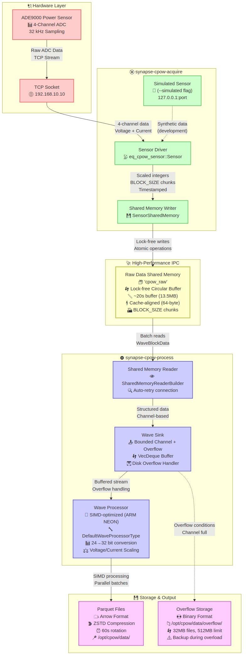
Data Flow
- Hardware Layer: ADE9000 sensor captures 4-channel power data at 32kHz
- Acquire Process: Reads sensor data via TCP and writes to shared memory
- Shared Memory IPC: High-performance lock-free circular buffer for inter-process communication
- Process Process: Reads from shared memory, processes with SIMD optimizations, outputs to Parquet files
- Storage: Compressed Parquet files with overflow handling
Key Features
Performance:
- Lock-free shared memory with atomic operations
- SIMD-optimized processing (ARM NEON)
- High-priority threads for real-time performance
- Cache-aligned data structures
- Zero-copy design where possible
Robustness:
- Graceful shutdown handling
- Connection retry logic
- Buffer overflow detection and recovery
- Data integrity verification
synapse-cpow-process Architecture
The synapse-cpow-process component reads raw sensor data from shared memory, transforms it through SIMD-optimized processing, and outputs structured Parquet files.

Core Data Flow
SensorDataRow (21 bytes)
    ↓ [SharedMemoryReader]
WaveBlockData batches
    ↓ [WaveSink buffering]
Bounded channel stream
    ↓ [24→32 bit conversion]
DataBuffer (i32 circular buffer)
    ↓ [SIMD scaling operations]
Scaled float32 data
    ↓ [Arrow serialization]
Parquet files (ZSTD compressed)
Channel Mapping
Channel 0: IA (Current A)   - iscale factor
Channel 1: VA (Voltage A)   - vscale factor
Channel 2: IB (Current B)   - iscale factor
Channel 3: VB (Voltage B)   - vscale factor
Channel 4: IC (Current C)   - iscale factor
Channel 5: VC (Voltage C)   - vscale factor
Channel 6: IN (Neutral)     - iscale factor
Detailed Documentation
CPOW Data Processing Pipeline
cpow_process_analysis.md
Level: Advanced/Expert
Complete architectural deep dive into the CPOW process binary (synapse-cpow-process):
- Data pipeline from sensor acquisition through Parquet file output
- Shared memory reader/writer implementation
- Arrow IPC integration for columnar data storage
- NEON optimization for ARM platforms
- Command-line interface and configuration options
- Error handling and recovery mechanisms
Key sections:
- Section 2: Data Pipeline Architecture
- Section 7: Processing Pipeline Detailed Walkthrough
- Section 10: Performance Considerations
Shared Memory Operations (eq-memops)
eq_memops_analysis.md
Level: Advanced/Expert | Recommended starting point
The eq-memops crate provides foundational shared memory abstractions:
- Generic
SharedMemoryAccesstrait and implementations ArrowSharedMemorylock-free multi-reader architectureSharedMemoryReaderpatterns and builder API- Multi-reader support (up to 16 concurrent readers)
- Memory layout, alignment, and atomic synchronization
- NEON optimization for ARM platforms
Key sections:
- Section 2: Arrow Shared Memory Implementation
- Section 3: Reader/Writer Patterns
- Section 7: Memory Layout & Synchronization
eq_memops_visuals.md
Level: Intermediate to Advanced | Companion to eq_memops_analysis.md
Visual ASCII diagrams covering:
- Data flow architecture
- Memory layout diagrams
- Writer-reader synchronization flowcharts
- State machines and error transitions
SUMMARY.txt
Plain text alternative to eq_memops_analysis.md with linear narrative flow.
Configuration & Deployment
MEMORY_CONFIG_REFERENCE.md
Level: Intermediate | Audience: DevOps, deployment engineers
Memory-related configuration parameters:
- DuckDB pool and query configuration
- Shared memory buffer sizing
- Connection limits and WebSocket configuration
- Memory budget analysis (current vs edge-optimized)
- Edge device configuration overrides
WebSocket Integration
WEBSOCKET_BATCH_AGGREGATION.md
WebSocket batch aggregation for real-time data streaming.
Reading Paths
New to the Codebase
- eq_memops_visuals.md - Visual overview
- eq_memops_analysis.md sections 1-4 - Foundational concepts
- cpow_process_analysis.md section 2 - Data flow understanding
- MEMORY_CONFIG_REFERENCE.md - Deployment considerations
Performance Optimization
- cpow_process_analysis.md section 10 - Performance Considerations
- eq_memops_analysis.md section 13 - Performance Characteristics
- MEMORY_CONFIG_REFERENCE.md - Configuration tuning
Debugging Issues
- cpow_process_analysis.md section 9 - Error Handling & Recovery
- eq_memops_analysis.md section 8 - Error Handling Hierarchy
- eq_memops_visuals.md section 8 - Error State Transitions
Quick Reference
Key Concepts
- WaveBlockData: 256-row blocks of 7-channel sensor data (8ms @ 32kHz)
- SensorSharedMemory: Raw 24-bit sensor data circular buffer
- ArrowSharedMemory: Lock-free multi-reader Arrow IPC shared memory
- DataBuffer: Conversion layer from 24-bit to 32-bit with batch views
- NEON optimization: ARM SIMD acceleration for data conversion
Critical Constants
N_ROWS_PER_BLOCK: 256 rowsSAMPLE_HZ: 32,000 HzN_CHANNELS: 7 (ia, va, ib, vb, ic, vc, i_n)ROWS_PER_BATCH: 320,000 rows (10 seconds)MAX_READERS: 16 concurrent readers
Key Source Files
eq-memops/src/ipc/arrow.rs: Arrow shared memory implementationeq-memops/src/ipc/reader.rs: Generic shared memory readersynapse-cpow/process/src/bin/default.rs: CPOW process binary entry pointeq-cpow/sensor/src/lib.rs: Sensor shared memory interface
Related Documentation
- PMON Pipeline - Power monitoring pipeline
- Unified Backend API - Backend API and server architecture
- Library Crates - Overview of Rust crates and dependencies
- Traits and Generics - Rust patterns used in the codebase
- Individual crate READMEs in
server/crates/directory
Last Reviewed: 2026-02-02
© 2026 EQ Systems Inc.
CPOW Process Binary Analysis
Synapse CPOW-Process: Data Pipeline & Implementation Deep Dive
Location: /mnt/code/dev/Rust/energy-quotient/pq-synapse/server/crates/synapse-cpow/process
1. OVERVIEW & ENTRY POINTS
Binary Configuration
- Binary Name:
cpow-process - Source:
src/bin/default.rs - Features:
force_no_neon: Disables ARM NEON optimization (forces fallback implementation)use_neon: Automatically enabled on ARM platforms (aarch64/arm)
Main Command-Line Architecture
cpow-process [OPTIONS] <COMMAND>

Global Options:
  --dev                    Enable development mode (custom shared memory naming)

Commands:
  default --verbose        Run the default wave processor
  parquet --output-dir     Parquet processor (future implementation)
Current Implementation Flow
The binary currently supports two execution paths:
- Production:
defaultcommand (–dev flag not set) - Development:
defaultcommand with –dev flag
2. DATA PIPELINE ARCHITECTURE
High-Level Data Flow
Shared Memory (Raw Sensor Data)
           ↓
    SharedMemoryReader Thread
           ↓
  WaveBlockData → flume channel
           ↓
    Processor Thread
           ↓
   Data Conversion & Scaling
           ↓
Arrow RecordBatch Creation
           ↓
   Parquet File Writer
           ↓
    Parquet Files on Disk
Processing Stages
Stage 1: Shared Memory Reading (eq-memops::reader)
- Thread: Reader spawned with priority -10 (high priority on Linux)
- Input:
SensorSharedMemory(circular buffer from CPOW acquire) - Output:
WaveBlockDatatuples sent via flume channel - Data Type:
WaveBlockData = (Vec<SensorDataRow>, u64)Vec<SensorDataRow>: 256 sensor samples (3 phases)u64: Timestamp (nanoseconds since UNIX epoch)
Key Implementation (eq-memops/src/ipc/reader.rs:SharedMemoryReader::run):
#![allow(unused)]
fn main() {
// Reads N_ROWS_PER_BLOCK (256) rows at a time
// Block contains 7 channels × 256 rows of 24-bit data
// Timestamp marks start of block
// Detects overrun conditions and buffer state changes
}
Stage 2: Data Buffering & Overflow Handling
- Component:
WaveSink(custom channel wrapper) - Purpose: Manages bounded channel + overflow buffer + disk fallback
- Buffer States:
Normal: Data flowing normallyBuffering: Channel full, using in-memory overflow bufferWritingToDisk: Overflow buffer full, writing to disk
- Configuration:
OVERFLOW_BUFFER_SIZE: 10 seconds of blocks (125 blocks)MAX_FILE_SIZE: 32 MB per overflow fileMAX_TOTAL_SIZE: 512 MB total overflow storage
Stage 3: Processing & Format Conversion
- Thread: Processor spawned with priority -10
- Input:
WaveBlockDatafrom channel (flume receiver) - Processing Engine:
DefaultWaveProcessorType
Key Transformations:
-
24-bit to 32-bit Conversion:
#![allow(unused)] fn main() { // Each SensorDataRow contains 7 channels of 24-bit data // Converted to i32 (sign-extended) fn i24_to_i32(bytes: [u8; 3]) -> i32 { if (bytes[2] & 0x80) != 0 { // Check sign bit (0xFF000000u32 | ...) as i32 // Negative (extend) } else { ((bytes[2] as u32) << 16 | ...) as i32 // Positive } } } -
Data Batching (
DataBufferfromeq-memops::batch):- Accumulates raw 24-bit data into 32-bit format
- Organizes by channel
- Batch size: configurable (default: 320,000 rows = 10 seconds @ 32 kHz)
-
Scaling & Arrow Conversion:
- Current/voltage scaling factors applied
- Conversion to Arrow arrays for columnar storage
- Schema:
[IA, VA, IB, VB, IC, VC, IN](7 Int32 fields)
Stage 4: Parquet File Writing
- Component:
ArrowIpc+ParquetWriter - Output Location:
$CPOW_DATA_DIR(from config) - File Format: Parquet with Zstandard compression
- Metadata Storage:
start_time: RFC3339 timestamp with nanosecond precisionvscale: Voltage scaling factoriscale: Current scaling factor
File Rotation Logic:
- Triggers when:
- Row count exceeds 1,920,000 rows (~60 seconds @ 32 kHz)
- 60 seconds elapsed (configurable)
- Timestamp discontinuity > 1 second detected
3. SHARED MEMORY INTERFACE
SensorSharedMemory Structure (eq-cpow/sensor)
Memory Layout (cache-line aligned):
┌─────────────────────────────┐
│  SensorSharedControl (64B)  │
│  - read_pos (atomic)        │
│  - write_pos (atomic)       │
│  - terminate_flag           │
│  - reader_active            │
│  - generation               │
├─────────────────────────────┤
│  SensorSharedData Header    │
│  - num_rows                 │
│  - vscale (f32)             │
│  - iscale (f32)             │
├─────────────────────────────┤
│  SensorDataRow[num_rows]    │  (21 bytes each, 256 rows/block)
│  ia, va, ib, vb, ic, vc, in│
│  (3 bytes each channel)     │
├─────────────────────────────┤
│  Timestamps[num_rows/256]   │  (8 bytes each, 1 per block)
└─────────────────────────────┘
Data Types
SensorDataRow (21 bytes, packed):
#![allow(unused)]
fn main() {
#[repr(C, packed)]
pub struct SensorDataRow {
    pub ia: [u8; 3],   // Phase A current
    pub va: [u8; 3],   // Phase A voltage
    pub ib: [u8; 3],   // Phase B current
    pub vb: [u8; 3],   // Phase B voltage
    pub ic: [u8; 3],   // Phase C current
    pub vc: [u8; 3],   // Phase C voltage
    pub i_n: [u8; 3],  // Neutral current
}
}
Key Constants:
N_ROWS_PER_BLOCK: 256 (= 1 frame × 64 rows/frame)BLOCK_SIZE: 5,376 bytes (256 rows × 21 bytes)BLOCK_DURATION: 8 milliseconds @ 32 kHzSAMPLE_HZ: 32,000 HzN_CHANNELS: 7
Reading Process
#![allow(unused)]
fn main() {
// In SharedMemoryReader::run()
loop {
    let rows_available = write_pos - read_pos;

    if rows_available >= N_ROWS_PER_BLOCK {
        // 1. Prepare data at read position
        let prepared_data = shared_mem.prepare_data_at(read_pos, N_ROWS_PER_BLOCK)?;
        // Returns: (Vec<SensorDataRow>, timestamp)

        // 2. Send to sink (channel)
        sink.try_consume(prepared_data)?;

        // 3. Advance read position
        read_pos = (read_pos + N_ROWS_PER_BLOCK) % num_rows;
    } else {
        sleep(Duration::from_micros(10));
    }
}
}
Buffer State Detection (metrics tracking):
- Normal: Standard operation
- OverrunRiskWarning: Buffer > 50% full (wrapped case)
- Overrun: Reader hasn’t kept up, data lost
- WritingToDisk: Overflow buffer being persisted
4. ARROW SHARED MEMORY IMPLEMENTATION (Partially Complete)
Status: TODO - Incomplete
Location: eq-memops/src/ipc/arrow.rs (lines 364+)
Architecture Design
ArrowSharedMemory Structure (proposed):
#![allow(unused)]
fn main() {
pub struct ArrowSharedMemory {
    shmem: Arc<Shmem>,
    schema: SchemaRef,
    control: *mut ArrowSharedControl,
    data_offset: usize,
    total_size: usize,
    reader_mode: ReaderMode,  // Single or Multi(MultiReaderState)
}
}
Control Structure (for lock-free multi-reader):
#![allow(unused)]
fn main() {
#[repr(align(64))]
pub struct ArrowSharedControl {
    write_pos: AtomicUsize,
    generation: AtomicI64,
    batch_infos: [BatchInfo; 1024],  // Up to 1024 batches
}

struct BatchInfo {
    offset: AtomicUsize,
    size: AtomicUsize,
    timestamp: AtomicI64,
}
}
Reader Control (multi-reader support):
#![allow(unused)]
fn main() {
#[repr(align(64))]
struct ReaderControl {
    positions: [AtomicUsize; 16],    // Up to 16 readers
    active: [AtomicUsize; 16],       // Reader active flags
}
}
Design Goals
- Lock-free operation: Uses compare-and-swap for coordination
- Multi-reader support: 16 concurrent readers maximum
- Arrow Record Batch streaming: Direct serialization to shared memory
- Circular buffer: Automatic wrapping when full
Implemented Methods
new(): Create/open shared memory region with schemawrite(): Write RecordBatch as Arrow IPC formatread(): Read batch by reader IDregister_reader(): Register new reader (returns ID)unregister_reader(): Deactivate reader
Known Issues (TODO markers)
#![allow(unused)]
fn main() {
todo!("Determine intended logic and fix inst of ArrowSharedMemory");  // Line 364
}
The initialization logic is incomplete - control pointer setup and boundary calculations need finalization.
Proposed Use Cases (Future)
- Live data streaming to web frontends via WebSocket
- Real-time analytics consumer processes
- Event detection system reading raw data simultaneously with file writing
5. NEON OPTIMIZATION (ARM-Specific)
Overview
The system uses ARM NEON (Single Instruction Multiple Data) instructions for high-performance 24-bit to 32-bit conversion and scaling.
Implementation
Location: eq-memops/src/neon_ops/
Rust Wrapper (conversion.rs):
#![allow(unused)]
fn main() {
pub fn i32_to_f32_scaled(input: &[i32], scale: f32) -> Vec<f32> {
    #[cfg(any(target_arch = "arm", target_arch = "aarch64"))]
    {
        convert_i32_to_f32_neon(input, scale)
    }

    #[cfg(not(any(target_arch = "arm", target_arch = "aarch64")))]
    {
        // Fallback for x86/other platforms
        input.iter().map(|&x| x as f32 * scale).collect()
    }
}
}
C Implementation (conversion.c):
- Uses ARM NEON intrinsics for batch conversion
- In-place transformation of i32 buffer to f32
- Handles scaling factor application
Build Integration (build.rs):
#![allow(unused)]
fn main() {
if (target.contains("aarch64") || target.contains("arm")) && !force_no_neon {
    cc::Build::new()
        .file("../../eq-memops/src/neon_ops/conversion.c")
        .compile("neon_ops");
    println!("cargo:rustc-cfg=feature=\"use_neon\"");
}
}
Force Disable:
cargo build --features force_no_neon
6. COMMAND-LINE OPTIONS & DEFAULT FLAG
Currently Supported Commands
default Command
cargo run --bin synapse-cpow-process -- default [OPTIONS]

Options:
  -v, --verbose    Enable verbose output during processing
Behavior:
- Reads from production shared memory path (no user suffix)
- Threads spawned with priority -10
- Metrics enabled by default
- Normal error handling with automatic recovery
default with --dev Flag
cargo run --bin synapse-cpow-process -- --dev default --verbose

Options:
  --dev                    Add user suffix to shared memory name
  -v, --verbose            Verbose mode in processor
Behavior:
- Loads config from database (
SynapseConfig::from_db_sync()) - Appends
_{USER}to shared memory name - Example:
raw_cpow_shmem_userinstead ofraw_cpow_shmem - Useful for development without interfering with production data
Future --default Flag (Not Yet Implemented)
The code structure suggests future support for a --default flag to select default processor behavior:
#![allow(unused)]
fn main() {
#[derive(Subcommand, Debug)]
enum ProcessorCommands {
    Default { .. },      // Current implementation
    Parquet { .. },      // Future: custom parquet output location
}
}
This would allow:
# Potential future syntax
cargo run --bin synapse-cpow-process -- --default
7. PROCESSING PIPELINE DETAILED WALKTHROUGH
Thread Initialization
Main Thread (src/bin/default.rs:main()):
#![allow(unused)]
fn main() {
// 1. Create channel for data flow
let (tx, rx) = flume::unbounded::<WaveBlockData>();

// 2. Create WaveSink with overflow handling
let sink = WaveSink::new(tx, OVERFLOW_BUFFER_SIZE)?;

// 3. Spawn reader thread
let reader_handle = spawn_thread::<_, _, _, WaveProcessError>(
    "shared_memory_reader",
    move || {
        // Set priority to -10 (high)
        setpriority(PRIO_PROCESS, 0, -10);

        // Build and run reader
        let mut reader = SharedMemoryReaderBuilder::<
            SensorSharedMemory,
            WaveSink,
            WaveBlockData
        >::default(sink)?
            .with_metrics(true)
            .build()?;

        reader.run(Arc::clone(&term_flag_ref))
    }
)?;

// 4. Spawn processor thread
let processor = ProcessorBuilder::new()
    .with_source(rx)
    .build()?;

let mut proc_runner = processor.into_runner()?;

let proc_handle = spawn_thread::<_, _, _, WaveProcessError>(
    "processor",
    move || {
        setpriority(PRIO_PROCESS, 0, -10);
        proc_runner.run_as::<DefaultWaveProcessorType>(
            Arc::clone(&terminate_flag)
        )
    }
)?;
}
Reader Thread Operation
Location: eq-memops/src/ipc/reader.rs:SharedMemoryReader::run()
#![allow(unused)]
fn main() {
// 1. Wait for writer to become active
while !terminate_flag.load(Ordering::SeqCst) {
    if self.shared_mem.is_writer_active() { break; }
    thread::sleep(Duration::from_secs(1));
}

// 2. Initialize read position (align to block boundary)
let mut read_pos = self.shared_mem.read_position();
read_pos = read_pos - (read_pos % N_ROWS_PER_BLOCK);
self.shared_mem.set_read_position(read_pos);

// 3. Main read loop
loop {
    let write_pos = self.shared_mem.write_position();
    let rows_available = (write_pos + num_rows - read_pos) % num_rows;

    if rows_available >= N_ROWS_PER_BLOCK {
        // Prepare data block
        let prepared_data = self.shared_mem.prepare_data_at(
            read_pos,
            N_ROWS_PER_BLOCK
        )?;

        // Send to sink
        match self.sink.try_consume(prepared_data) {
            Ok(()) => {
                read_pos = (read_pos + N_ROWS_PER_BLOCK) % num_rows;
                self.shared_mem.set_read_position(read_pos);
            }
            Err(_) => {
                // Handle overflow - written to buffer/disk
            }
        }
    } else {
        thread::sleep(Duration::from_micros(10));
    }

    if terminate_flag.load(Ordering::Acquire) { break; }
}
}
Processor Thread Operation
Location: eq-processing/src/default.rs:DefaultWaveProcessorType::run()
#![allow(unused)]
fn main() {
// 1. Initialize Arrow IPC writer with schema
let schema = Arc::new(Schema::new(vec![
    Field::new("IA", DataType::Int32, false),
    Field::new("VA", DataType::Int32, false),
    // ... 7 channels total
]));

let mut arrow_ipc = ArrowIpc::new(schema, dest, scaler)?;
arrow_ipc.initialize_writer()?;

// 2. Main processing loop
loop {
    // Check if rotation needed (every 1 second)
    if last_rotate_check.elapsed() >= Duration::from_secs(1) {
        if arrow_ipc.check_rotation_needed()? {
            arrow_ipc.rotate()?;  // Close file, open new one
        }
        last_rotate_check = std::time::Instant::now();
    }

    // Receive block from channel
    match self.processor.source.recv() {
        Ok((rows, timestamp)) => {
            // Create buffer and convert to Arrow format
            let mut buffer = DataBuffer::new(rows.len());
            buffer.push_datarows(&rows)?;

            let mut view = buffer.raw_view(buffer.len())?;

            // Get first batch
            if let Some(batch) = view.next_result()? {
                // Check for timestamp discontinuity (>1s gap)
                if timestamp > (last_ts + 1_000_000_000) {
                    tracing::warn!("Timestamp discontinuity - rotating file");
                    arrow_ipc.rotate()?;
                }

                // Write to parquet
                arrow_ipc.write_batch(&batch, timestamp)?;
                last_ts = timestamp;
            }
        }
        Err(ChannelError::Empty) => {
            thread::sleep(Duration::from_micros(10));
        }
        Err(ChannelError::Disconnected) => break,
    }

    if terminate_flag.load(Ordering::Acquire) { break; }
}
}
Data Conversion Pipeline
24-bit to 32-bit in DataBuffer:
#![allow(unused)]
fn main() {
pub fn push_datarows(&mut self, rows: &[SensorDataRow]) -> Result<usize, BatchError> {
    for row in rows {
        let offset = self.write_pos * N_CHANNELS;

        // Unroll field access - direct 24→32 conversion
        self.data[offset]     = i24_to_i32(row.ia);  // Ch0: IA
        self.data[offset + 1] = i24_to_i32(row.va);  // Ch1: VA
        self.data[offset + 2] = i24_to_i32(row.ib);  // Ch2: IB
        self.data[offset + 3] = i24_to_i32(row.vb);  // Ch3: VB
        self.data[offset + 4] = i24_to_i32(row.ic);  // Ch4: IC
        self.data[offset + 5] = i24_to_i32(row.vc);  // Ch5: VC
        self.data[offset + 6] = i24_to_i32(row.i_n); // Ch6: IN

        self.write_pos = (self.write_pos + 1) % self.capacity;
        self.len += 1;
    }
    Ok(n_rows)
}
}
Arrow RecordBatch Creation:
#![allow(unused)]
fn main() {
impl ProcessorSink<WaveBlockData> for ArrowIpc<...> {
    fn write_batch(&mut self, batch: &BatchSlice<i32>, timestamp: u64) {
        // Apply scaling to each channel
        let channel_arrays: Vec<Arc<dyn Array>> = batch
            .channels
            .par_iter()
            .enumerate()
            .map(|(channel_idx, channel_data)| {
                let scale_factor = self.scaler.scale_factor(channel_idx);

                // Scale: current (i%2==0) or voltage (i%2==1)
                let scaled_values: Vec<f32> = channel_data
                    .iter()
                    .map(|&v| scale_factor * v as f32)
                    .collect();

                Arc::new(arrow::array::Float32Array::from(scaled_values))
                    as Arc<dyn Array>
            })
            .collect();

        // Create batch and write to parquet
        let record_batch = RecordBatch::try_new(
            self.schema.clone(),
            channel_arrays
        )?;

        self.writer.write_batch(&record_batch)?;
    }
}
}
8. PARQUET OUTPUT CONFIGURATION
File Format & Compression
Writer Configuration (ParquetWriter::init):
#![allow(unused)]
fn main() {
let props = WriterProperties::builder()
    .set_encoding(Encoding::DELTA_BINARY_PACKED)
    .set_compression(Compression::from(config.cpow.parquet.compression))
    .set_max_row_group_size(ROWS_PER_BATCH)
    .set_data_page_row_count_limit(ROWS_PER_BATCH / 4)
    .set_data_page_size_limit(PARQUET_DATA_PAGE_SIZE_LIMIT)
    .set_dictionary_page_size_limit(PARQUET_DICTIONARY_PAGE_SIZE_LIMIT)
    .set_statistics_enabled(EnabledStatistics::Page)
    .set_key_value_metadata(Some(metadata))
    .build();
}
Constants (ParquetConstants):
ROWS_PER_BATCH: 320,000 rows (10 seconds @ 32 kHz)TERMINATION_CHECK_ROWS: 3,200 rows (100 ms)PARQUET_DATA_PAGE_SIZE_LIMIT: 83,886,080 bytes (~80 MB)PARQUET_DICTIONARY_PAGE_SIZE_LIMIT: 16,384 bytes (~16 KB)
File Structure
Filename Format:
{CPOW_DATA_DIR}/{YYYYMMDD_HHMMSS}.parquet
Metadata Key-Value Pairs:
start_time: RFC3339 timestamp (nanosecond precision)vscale: Voltage scale factor (float)iscale: Current scale factor (float)
Row Groups:
- Size: 320,000 rows per group
- Compression: Zstandard (configurable)
- Encoding: Delta Binary Packed for integers
9. ERROR HANDLING & RECOVERY
Error Types
WaveProcessError hierarchy:
├─ Processing: Processor error
├─ Memops: Memory operations error
├─ Ipc: Inter-process communication error
├─ SharedMemory: Shared memory initialization error
├─ SharedMemoryReader: Reader-specific error
├─ Sensor: Sensor error
├─ Parquet: Parquet file error
├─ LedControl: LED control error
├─ DiskManager: Disk management error
├─ Channel: Custom channel error
│  ├─ Disconnected: Channel severed
│  ├─ Full: Channel at capacity
│  ├─ Timeout: Read timeout
│  ├─ BufferOverflow: Overflow buffer full
│  └─ DiskWrite: Failed to write overflow data
├─ Thread: Thread spawning error
├─ ThreadExecution: Thread runtime error
├─ Initialization: Startup error
├─ Configuration: Config loading error
├─ Io: Standard I/O error
└─ Other: Generic error
Overflow Handling Sequence
Normal Channel Send
    ↓
Channel Full? → Yes → handle_overflow()
    ↓ No
    Success

Overflow Handling:
  1. Try to pop from overflow buffer → primary channel
  2. If buffer not full → add block to buffer
  3. If buffer full → try_send to disk writer
Metrics & Monitoring
Reader Metrics (ReaderMetrics):
blocks_processed: Total blocks readlast_read_time: UNIX timestamp of last readshared_mem_buffer_state: Current shared memory statesink_buffer_state: Current channel stateoverflow_count: Times channel was fullread_errors: Total read failuresprocessing_rate: Blocks per second
10. PERFORMANCE CONSIDERATIONS
Thread Priorities
- Both reader and processor threads set to priority -10 (Linux)
- Higher priority = lower latency, prevents preemption
Memory Alignment
SensorSharedControl: 64-byte cache-line alignedSensorSharedData: 64-byte cache-line aligned- Minimizes false sharing between reader and processor
Batching Strategy
- Reader: Reads 256 rows per transaction (8 ms)
- Processor: Batches to 320,000 rows (10 seconds) before writing
- Channel: Unbounded primary + 1,250-row overflow buffer
NEON Optimization Impact
- ARM platforms: 4x+ speedup on 24→32-bit conversion
- Fallback: Automatic scalar processing on other architectures
- Force disable: Use
force_no_neonfeature for benchmarking
File I/O Strategy
- Asynchronous rotation: Checks every 1 second
- Triggers: Row count threshold OR time-based (60 sec)
- Timestamp discontinuity: Immediate rotation on > 1 second gap
- Compression: Zstandard (configurable level)
11. CONFIGURATION INTEGRATION
SynapseConfig Integration
#![allow(unused)]
fn main() {
// From config database
let config = SynapseConfig::from_db_sync()?;

// Used for:
- config.cpow.processing.shared_memory.raw.name
- config.cpow.parquet.compression
- Event detection parameters
- Processing thresholds
}
Development Mode User Suffix
#![allow(unused)]
fn main() {
let raw_shmem_name = if parsed.dev {
    let user = std::env::var("USER").unwrap_or_else(|_| "user".to_string());
    format!("{}_{}", config.cpow.processing.shared_memory.raw.name, user)
} else {
    config.cpow.processing.shared_memory.raw.name.clone()
};
}
12. KEY FILES & MODULES REFERENCE
| Module | Location | Purpose |
|---|---|---|
WaveSink | synapse-cpow/process/src/wave_sink.rs | Channel + overflow buffer management |
SharedMemoryReader | eq-memops/src/ipc/reader.rs | Generic shared memory reading |
DefaultWaveProcessorType | eq-processing/src/default.rs | Main processor logic |
ArrowIpc | eq-memops/src/ipc/arrow.rs | Arrow serialization + file writing |
ParquetWriter | eq-processing/src/default.rs | Parquet file writer |
SensorSharedMemory | eq-cpow/sensor/src/lib.rs | Shared memory interface |
DataBuffer | eq-memops/src/ipc/batch.rs | Data batching & conversion |
WaveDataScaler | eq-cpow/data/src/scale.rs | Channel scaling logic |
NEON ops | eq-memops/src/neon_ops/ | ARM SIMD acceleration |
13. SUMMARY: DATA FLOW WITH NUMBERS
Sensor @ 32 kHz → 7 channels × 24-bit data
        ↓
Shared Memory (circular buffer, 256-row blocks)
        ↓
Reader Thread (block every 8 ms, async priority -10)
        ↓
256 rows/block → WaveBlockData tuple
        ↓
Flume Channel (unbounded + 10-sec overflow buffer)
        ↓
Processor Thread (async priority -10)
        ↓
24-bit → 32-bit conversion (NEON accelerated on ARM)
        ↓
320,000-row batch accumulation (10 seconds)
        ↓
Arrow RecordBatch with scaling applied
        ↓
Parquet File Writing (Zstandard compression)
        ↓
1,920,000-row file limit OR 60-second rotation
        ↓
Timestamped Parquet files on disk (~YYYYMMDD_HHMMSS.parquet)
14. FUTURE ENHANCEMENTS & TODOS
-
Arrow Shared Memory (Partially Complete)
- Complete
ArrowSharedMemory::new()initialization - Implement multi-reader batch consumption
- Integration with web services
- Complete
-
Parquet Processor Command
- Custom output directory support
- Alternative compression strategies
- File naming conventions
-
Metrics Enhancement
- Export to Prometheus
- Real-time performance dashboard
- Per-channel statistics
-
Overflow Handler Improvements
- Memory-mapped files instead of standard I/O
- Compression for overflow data
- Automatic cleanup of old overflow files
-
Configuration Enhancements
- Per-command configuration overrides
- Runtime parameter adjustment
- Hot-reload support
© 2026 EQ Systems Inc.
Memory Configuration Reference for Edge Device Deployment
This document catalogs all memory-related configurations in the Synapse RAG system for edge device optimization.
NOTE: Some of these values must be reduced prior to running on i.mx8M Plus gateway
Critical Memory Allocations
1. DuckDB Database Configuration (eq-db/src/duckdb/config.rs)
Pool Configuration
#![allow(unused)]
fn main() {
pub struct DuckDBPoolConfig {
    memory_limit: String,           // DEFAULT: "6GB" ⚠️ HIGH MEMORY
    threads: usize,                 // DEFAULT: 6
    max_connections: usize,         // DEFAULT: 10
    min_connections: usize,         // DEFAULT: 2
    max_concurrent_queries: usize,  // DEFAULT: 100
}
}
Query Configuration
#![allow(unused)]
fn main() {
pub struct DuckDBQueryConfig {
    batch_size: usize,           // DEFAULT: 10,000 rows
    max_result_size: usize,      // DEFAULT: 100MB ⚠️ HIGH MEMORY
    statement_timeout: Duration, // DEFAULT: 5 minutes
}
}
Data Configuration
#![allow(unused)]
fn main() {
pub struct DuckDBDataConfig {
    metadata_cache_size: usize,  // DEFAULT: 256MB ⚠️ MEMORY USAGE
    max_file_handles: usize,     // DEFAULT: 1,000
}
}
EDGE DEVICE RECOMMENDATIONS:
memory_limit: Reduce to “1GB” or “2GB” maxmax_connections: Reduce to 2-4max_result_size: Reduce to 10-50MBmetadata_cache_size: Reduce to 64MB or 128MB
2. RAG Core Configuration (rag-core/src/config.rs)
Context Store Configuration
#![allow(unused)]
fn main() {
pub struct ContextStoreConfig {
    max_chunk_tokens: usize,     // DEFAULT: 1,024
    max_total_tokens: usize,     // DEFAULT: 8,192
    compression_threshold: f32,   // DEFAULT: 0.8
    max_context_age_seconds: u64, // DEFAULT: 86,400 (24 hours)
}
}
Tool Configuration
#![allow(unused)]
fn main() {
pub struct ToolConfig {
    max_memory_mb: usize,        // DEFAULT: 512MB (DuckDB), 256MB (Plot) ⚠️
    timeout_seconds: u64,        // DEFAULT: 30-60s
}

pub struct ToolRegistryConfig {
    max_output_size_bytes: usize, // DEFAULT: 10MB ⚠️
}
}
Database Backend
#![allow(unused)]
fn main() {
pub struct DatabaseBackendConfig {
    max_connections: usize,      // DEFAULT: 10
    connection_string: Option<String>, // DEFAULT: ":memory:" ⚠️
}
}
EDGE DEVICE RECOMMENDATIONS:
max_total_tokens: Reduce to 4,096max_memory_mb: Reduce DuckDB to 128MB, Plot to 64MBmax_output_size_bytes: Reduce to 1-5MBmax_connections: Reduce to 2-4
3. Embedding Configuration (eq-semantic/src/embedding/config.rs)
Model Memory Estimation
#![allow(unused)]
fn main() {
impl EmbeddingConfig {
    fn estimated_memory_mb(&self) -> usize {
        match self.model_name.as_str() {
            "all-MiniLM-L6-v2" => 90,   // 90MB model ✓ EDGE FRIENDLY
            "all-mpnet-base-v2" => 420, // 420MB model ⚠️ HIGH MEMORY
            _ => 200, // Default estimate
        }
    }
}
}
Batch Processing
#![allow(unused)]
fn main() {
pub struct EmbeddingConfig {
    batch_size: usize,              // DEFAULT: 32, MAX: 1000 ⚠️
    max_sequence_length: usize,     // DEFAULT: 256, MAX: 512
    normalize_embeddings: bool,     // DEFAULT: true
}

pub struct ConcurrentConfig {
    batch_size: usize,              // DEFAULT: 32
    channel_buffer_size: usize,     // DEFAULT: 4 batches
    parquet_chunk_size: usize,      // DEFAULT: 1,000 records ⚠️
}
}
Memory Optimization Methods
#![allow(unused)]
fn main() {
// Low memory configuration
pub fn low_memory() -> ConcurrentConfig {
    batch_size: 16,           // Reduced from 32
    channel_buffer_size: 2,   // Reduced from 4
    parquet_chunk_size: 500,  // Reduced from 1000
}

// Memory per batch estimation
fn optimal_batch_size(&self, available_memory_mb: usize) -> usize {
    let memory_per_item = match self.embedding_dimension() {
        384 => 2,  // ~2MB per batch item (MiniLM)
        768 => 4,  // ~4MB per batch item (MPNet) ⚠️
        _ => 3,
    };
}
}
EDGE DEVICE RECOMMENDATIONS:
- Use
all-MiniLM-L6-v2model (90MB vs 420MB) batch_size: 8-16 (vs default 32)channel_buffer_size: 2 (vs default 4)parquet_chunk_size: 500 (vs default 1000)
4. RAG Engine Model Loading (synapse-rag/engine/src/model.rs)
Model Files and Caching
#![allow(unused)]
fn main() {
// Local model paths - potential high disk usage
let local_base = PathBuf::from("/mnt/code/dev/models/qwen2.5-3b");

// Cache directory
fn get_cache_dir(model_name: &str) -> Result<PathBuf> {
    dirs::cache_dir()
        .join("synapse-rag")
        .join("models")
        .join(model_name.replace("/", "_")); // ⚠️ DISK USAGE
}
}
Model Configuration
#![allow(unused)]
fn main() {
pub struct ModelConfig {
    vocab_size: usize,              // DEFAULT: 151,936
    hidden_size: usize,             // DEFAULT: 2,048
    intermediate_size: usize,       // DEFAULT: 11,008 ⚠️
    num_hidden_layers: usize,       // DEFAULT: 36 ⚠️
    max_position_embeddings: usize, // DEFAULT: 32,768 ⚠️
}
}
EDGE DEVICE RECOMMENDATIONS:
- CRITICAL: Switch to smaller model (1B params vs 3B)
- Clear model cache regularly
- Use quantized models if available
- Consider using Ollama backend instead of direct model loading
5. Shared Memory Configuration (synapse-config/src/schema/config-template.yml)
CPOW Raw Data Buffer
shared_memory:
  raw:
    size: 13520100        # 20s of raw sensor data (~13MB) ⚠️
    name: "cpow_raw"
  # processed:
  #   size: 18874368      # 18MB for processed data ⚠️ (DISABLED)
Connection Limits
connection_limit:
  max_connections_per_ip: 20              # ⚠️ HIGH
  max_incoming_data_per_minute: 1048576   # 1MB/min ⚠️
  max_message_size: 1048576               # 1MB ⚠️

ws:
  max_connections: 10                     # WebSocket connections ⚠️
EDGE DEVICE RECOMMENDATIONS:
shared_memory.raw.size: Reduce to 6760050 (10s vs 20s)max_connections_per_ip: Reduce to 5-10ws.max_connections: Reduce to 2-5
Memory Budget Summary for Edge Device
Current Default Configuration (Estimated)
- DuckDB: 6GB + 256MB cache = 6.25GB ⚠️
- Embedding Model: 420MB (MPNet) ⚠️
- RAG Model: 3B params ≈ 6-12GB ⚠️
- Shared Memory: 13MB + 18MB = 31MB
- Tool Memory: 512MB + 256MB = 768MB
- Connection Buffers: ~100MB
- TOTAL: ~13-19GB ⚠️ EXCESSIVE FOR EDGE
Recommended Edge Configuration
- DuckDB: 1GB + 64MB cache = 1.06GB ✓
- Embedding Model: 90MB (MiniLM) ✓
- RAG via Ollama: 0MB (external process) ✓
- Shared Memory: 6.5MB + 0MB = 6.5MB ✓
- Tool Memory: 128MB + 64MB = 192MB ✓
- Connection Buffers: ~50MB ✓
- TOTAL: ~1.4GB ✓ EDGE SUITABLE
Configuration Override Files
Edge Device Config Override (edge-config.yml)
# Override for edge deployment
duckdb:
  memory_limit: "1GB"
  max_connections: 4
  max_result_size: 50MB
  metadata_cache_size: 64MB

embedding:
  model_name: "sentence-transformers/all-MiniLM-L6-v2"
  batch_size: 16
  channel_buffer_size: 2

rag:
  use_ollama: true  # External process, no direct model loading
  ollama_endpoint: "http://localhost:11434"

tools:
  duckdb:
    max_memory_mb: 128
  plot:
    max_memory_mb: 64

shared_memory:
  raw:
    size: 6760050  # 10s instead of 20s

connection_limit:
  max_connections_per_ip: 5
  ws:
    max_connections: 3
Monitoring and Alerts
Memory Usage Monitoring Points
- DuckDB Pool: Track active connections and memory usage
- Embedding Model: Monitor batch processing memory spikes
- Shared Memory: Monitor buffer fill rates
- Tool Execution: Track peak memory per tool execution
- Connection Pools: Monitor connection count and buffer sizes
Critical Memory Thresholds for Edge
- Total System: Stay under 2GB total usage
- Single Process: No process should exceed 512MB
- DuckDB: Monitor query result sizes
- Embedding: Watch for batch size memory spikes
- Shared Memory: Alert on buffer overruns
Next Steps
- Immediate: Switch to Ollama backend to eliminate direct model loading
- Configuration: Apply edge-optimized configuration overrides
- Testing: Validate memory usage under load with monitoring
- Optimization: Profile actual usage patterns and adjust accordingly
© 2026 EQ Systems Inc.
Synapse Power Monitor (PMON) Architecture
Sensor → Zenoh → PMON-DAQ → Storage
The Synapse Power Monitor (PMON) pipeline provides a distributed power quality monitoring system using Zenoh middleware for real-time data streaming and processing.

Data Flow Overview:
- Hardware/Simulation Layer: Physical sensors or simulation generates power quality measurements
- Zenoh Publisher: Data published to Zenoh middleware with topic-based routing
- PMON Subscriber: Receives power quality data via Zenoh pub/sub mechanisms
- Data Processing: Deserializes and validates power quality measurements
- Storage Backend: Writes data to Avro files with configurable rotation policies
- Management Interface: Web API for monitoring and control operations
Key Architecture Features:
- Zenoh Middleware: Decentralized pub/sub with automatic discovery and routing
- Flexible Data Sources: Supports both real sensors and high-fidelity simulation
- Pluggable Storage: Configurable Avro backend with compression and rotation
- Builder Pattern: Type-safe configuration with compile-time sensor mode selection
- Async Runtime: Full Tokio integration for concurrent operations
- Graceful Shutdown: Signal handling with proper resource cleanup
Reliability Features:
- Connection Resilience: Automatic Zenoh session recovery and retry logic
- Data Validation: Schema-enforced deserialization with error handling
- File Rotation: Time/size-based file management with overflow protection
- Configuration Management: Centralized config with environment-specific defaults
- Comprehensive Logging: Structured tracing with configurable log levels
synapse-pmon: Data Flow and Type Architecture
The synapse-pmon system processes power quality measurements through a Zenoh-based distributed architecture, supporting both real-time sensor data and high-fidelity simulation modes.

Core Data Flow
PowerQualityData (simulation/sensor)
    ↓ [Zenoh Publisher]
Zenoh Topic: "sim_sensor/power_quality"
    ↓ [Network/IPC Transport]
Zenoh Subscriber (FIFO Channel)
    ↓ [Bincode Deserializer]
PowerQualityData Record
    ↓ [Avro Writer Backend]
Compressed Avro Files (ZSTD)
Key Data Types
#![allow(unused)]
fn main() {
// Core power quality measurement structure
#[derive(Debug, Serialize, Deserialize, AvroSchema, Encode, Decode)]
pub struct PowerQualityData {
    pub time_us: i64,                           // Microsecond timestamp
    pub freq: f32,                              // System frequency (Hz)
    pub phase_a: Measurements,                  // Phase A measurements
    pub phase_b: Option<Measurements>,          // Phase B (optional)
    pub phase_c: Option<Measurements>,          // Phase C (optional)
    pub nirms: f32,                            // Neutral current RMS
}

// Individual phase measurements
#[derive(Debug, Serialize, Deserialize, AvroSchema, Encode, Decode)]
pub struct Measurements {
    pub vrms: f32,   // RMS voltage
    pub irms: f32,   // RMS current
    pub watt: f32,   // Active power
    pub fvrms: f32,  // Fundamental RMS voltage
    pub firms: f32,  // Fundamental RMS current
    pub fwatt: f32,  // Fundamental active power
    pub fvar: f32,   // Fundamental reactive power
}

// System configuration variants
#[derive(Debug, Serialize, Deserialize, Default, AvroSchema)]
pub enum PhaseVariants {
    Single,    // Single-phase system
    Two,       // Two-phase system
    #[default]
    Three,     // Three-phase system
}
}
Processing Architecture
1. Data Ingestion
- Zenoh Publisher: Publishes
PowerQualityDatato"sim_sensor/power_quality"topic - FIFO Channel: Buffered subscriber with configurable queue depth (default: 1024)
- Session Management: Automatic connection handling with retry policies
2. Data Transformation
- Bincode Deserialization: High-performance binary deserialization from Zenoh payload
- Schema Validation: Compile-time type safety with Avro schema enforcement
- Error Recovery: Robust error handling with detailed logging and continue-on-error semantics
3. Storage Backend
- Avro Writer: Schema-based columnar storage with ZSTD compression
- File Rotation: Configurable policies (time, size, count) for data management
- Directory Structure: Organized output with configurable base directories
Sensor Modes and Builder Pattern
#![allow(unused)]
fn main() {
// Type-safe builder pattern with sensor mode markers
impl<W> PowerMonitorBuilder<W, RealSensor> {
    pub fn new() -> Self { /* Real sensor configuration */ }
    pub fn with_sim(self) -> PowerMonitorBuilder<W, SimulationSensor> { /* Switch to simulation */ }
}

impl<W> PowerMonitorBuilder<W, SimulationSensor> {
    pub async fn build(self) -> Result<PowerMonitor<W>, PowerMonitorError> {
        // Includes sensor simulation setup
    }
}

// Runtime sensor selection
pub struct PowerMonitor<W: WriteBackend> {
    zenoh_session: Arc<Session>,
    sub_channel: Option<Subscriber<FifoChannelHandler<Sample>>>,
    writer: W,
    sensor: Option<Sensor<PmonSimSensor<'static>>>,    // Only for simulation
    sensor_handle: Option<tokio::task::JoinHandle<()>>, // Async sensor task
    is_simulation: bool,
    is_connection_terminated: bool,
}
}
Zenoh Configuration
#![allow(unused)]
fn main() {
// Default Zenoh session configuration
let mut config = zenoh::config::Config::default();

config.insert_json5("connect/endpoints", r#"["tcp/127.0.0.1:7447"]"#)?;
config.insert_json5("connect/timeout_ms", r#"{"peer": -1}"#)?;

// Topic-based subscription
let subscriber = session
    .declare_subscriber("sim_sensor/power_quality")
    .with(FifoChannel::new(1024))
    .wait()?;
}
Error Handling & Performance
- Connection Management: Automatic Zenoh session recovery with exponential backoff
- Data Integrity: Schema validation prevents malformed data from corrupting storage
- Async Processing: Non-blocking I/O with proper task isolation
- Resource Cleanup: Graceful shutdown with proper resource deallocation
- Memory Management: Bounded channels prevent memory exhaustion under load
Configuration Examples
#![allow(unused)]
fn main() {
// Writer configuration with rotation
let writer_config = WriterConfig::<AvroConfig>::builder()
    .with_writer_config(AvroConfig::default())
    .with_compression(CompressionConfig::default())
    .with_file_rotation(RotationPolicy::Size(1500))      // Rotate at 1500 bytes
    // .with_file_rotation(RotationPolicy::Time(Duration::from_secs(60)))  // Time-based
    .with_base_dir(PathBuf::from("./data"))
    .build()?;

// Simulation sensor setup
let sensor = SensorBuilder::<PmonSimSensor, PowerQualityGenerator>::new()
    .with_config(SynapseConfig::new_with_defaults())
    .with_data_generator(PowerQualityGenerator)
    .build()?;
}
Binary Targets
pmon (Power Monitor):
- Production binary for real sensor data processing
- Configured for continuous operation with proper signal handling
- Supports both simulation and real sensor modes
sim (Simulation):
- Development/testing binary with built-in pub/sub demonstration
- Shows both publisher and subscriber behavior in single process
- Useful for system validation and integration testing
Integration Points
- System Service: Systemd integration for production deployment
- Config Management: Centralized configuration with environment overrides
- Monitoring: Structured logging with configurable verbosity levels
© 2026 EQ Systems Inc.
Unified Backend API Documentation
The unified-backend is a high-performance Rust API server built on Actix-web that provides REST and WebSocket endpoints for real-time power quality monitoring. It serves as the central data gateway for the EQ Synapse platform.
Architecture Overview
Technology Stack
- Web Framework: Actix-web 4.11.0 (async, actor-based)
- Database: DuckDB (persistent Arrow-optimized storage)
- Data Format: Apache Arrow IPC (zero-copy, columnar)
- Serialization: Arrow IPC (Inter-Process Communication)
- WebSocket: Actix-web-actors with custom session management
- Shared Memory: ArrowSharedMemory for live streaming
Server Configuration
- Host:
0.0.0.0 - Port:
8080 - Workers: 2 Actix HTTP workers
- Worker Pool: 1 data processing worker (configurable)
- Keep-Alive: 75 seconds
Middleware Stack
- CORS: Allow any origin, method, header (supports credentials)
- Logger: Request/response logging
- Compress: Response compression (gzip, deflate, brotli)
API Base Path
All endpoints are prefixed with /api/v1
Core Concepts
Apache Arrow IPC Format
All HTTP data responses use Apache Arrow IPC (Inter-Process Communication) format:
Content-Type: application/vnd.apache.arrow.stream
Benefits:
- Zero-copy deserialization
- Language-agnostic (Python, JavaScript, Rust, C++)
- Columnar format (efficient for analytics)
- Preserves schema and data types
Client Libraries:
- JavaScript:
apache-arrownpm package - Python:
pyarrowpackage - Rust:
arrowcrate
Worker Pool Architecture
Requests are processed by a worker pool with:
- LRU Cache: 60-second TTL, 1000 entries
- Query Timeout: 30 seconds
- Data Strategies:
- Parquet: Historical data (>24h old)
- InMemory: Live data (<24h old)
- Hybrid: Queries spanning both timeframes
Data Sources
- DuckDB (Persistent): Parquet-backed tables for historical data
- Shared Memory (Live): ArrowSharedMemory for real-time CPOW streaming
- Event Logs: JSON files in
events/{device_id}/directories
REST API Endpoints
Health & Status
GET /health
Simple health check endpoint.
Response:
200 OK
"Server is healthy"
CPOW (Continuous Point-on-Wave) Endpoints
GET /api/v1/devices/{id}/cpow/data
Query historical CPOW waveform data.
Path Parameters:
id(string): Device identifier (e.g., “wave001”)
Query Parameters:
start_time(optional): ISO 8601 timestamp in UTCend_time(optional): ISO 8601 timestamp in UTCmetrics(optional): Comma-separated metric nameslimit(optional): Maximum number of rows to return
Response:
- Content-Type:
application/vnd.apache.arrow.stream - Body: Arrow IPC binary stream
Example Request:
curl "http://localhost:8080/api/v1/devices/wave001/cpow/data?start_time=2026-01-01T00:00:00Z&limit=10000" \
  -H "Accept: application/vnd.apache.arrow.stream"
Python Example:
import requests
import pyarrow as pa

response = requests.get(
    "http://localhost:8080/api/v1/devices/wave001/cpow/data",
    params={"start_time": "2026-01-01T00:00:00Z", "limit": 10000}
)
table = pa.ipc.open_stream(response.content).read_all()
df = table.to_pandas()
print(df.head())
Error Responses:
404: Device not found or no data available400: Invalid query parameters408: Query timeout (>30 seconds)500: Internal server error
GET /api/v1/devices/{id}/cpow_data_latest
Get the most recent CPOW data for a device.
Response:
- Content-Type:
application/vnd.apache.arrow.stream - Body: Arrow IPC binary with latest waveform data
GET /api/v1/devices/{id}/cpow_data_directional
Query CPOW data directionally from a specific timestamp.
Query Parameters:
from_timestamp(required): Unix microsecondsdirection(required): “ascending” or “descending”limit(optional): Row limit (default: 640,000)
Example:
curl "http://localhost:8080/api/v1/devices/wave001/cpow_data_directional?from_timestamp=1735689600000000&direction=descending&limit=100000"
GET /api/v1/devices/cpow/list_files
List available CPOW parquet files.
Response:
{
  "files": [
    "cpow_2026_01_01.parquet",
    "cpow_2026_01_02.parquet"
  ]
}
Note: Excludes the most recent file (may be actively written to).
POST /api/v1/devices/cpow/plot_with_file_name
Load CPOW data from a specific parquet file.
Request Body:
{
  "file_name": "cpow_2026_01_01.parquet"
}
Response:
- Content-Type:
application/vnd.apache.arrow.stream
Security: Path traversal protection (rejects .., /, \ in filenames).
PMON (Power Monitoring) Endpoints
GET /api/v1/devices/{id}/pmon/data
Query historical PMON aggregate data.
Query Parameters:
start_time(optional): ISO 8601 timestamp in UTCend_time(optional): ISO 8601 timestamp in UTCmetrics(optional): Comma-separated field nameslimit(optional): Maximum rows to return
Available Metrics:
| Category | Metrics |
|---|---|
| Voltage (RMS) | AVRMS, BVRMS, CVRMS |
| Current (RMS) | AIRMS, BIRMS, CIRMS, NIRMS |
| Real Power | AWATT, BWATT, CWATT |
| Fundamental Voltage | AFVRMS, BFVRMS, CFVRMS |
| Fundamental Current | AFIRMS, BFIRMS, CFIRMS |
| Fundamental Power | AFWATT, BFWATT, CFWATT |
| Reactive Power | AFVAR, BFVAR, CFVAR |
| Frequency | FREQ |
Example:
import requests
import pyarrow as pa

response = requests.get(
    "http://localhost:8080/api/v1/devices/wave001/pmon/data",
    params={
        "start_time": "2026-01-01T00:00:00Z",
        "end_time": "2026-01-01T01:00:00Z",
        "metrics": "AVRMS,FREQ",
        "limit": 10000
    }
)
table = pa.ipc.open_stream(response.content).read_all()
df = table.to_pandas()
POST /api/v1/devices/{id}/thumbnail
Get thumbnail/preview data for a single PMON field.
Request Body:
{
  "field": "AVRMS",
  "limit": 1000,
  "timeRange": 3600,
  "startTime": "2026-01-01T00:00:00Z",
  "endTime": "2026-01-01T01:00:00Z"
}
Parameters:
field(required): Single PMON field name (e.g., “AVRMS”, “FREQ”)limit(optional): Row limit (default: 1000)timeRange(optional): Seconds from now (ignored if start/end provided)startTime(optional): ISO 8601 timestampendTime(optional): ISO 8601 timestamp
Response:
- Content-Type:
application/vnd.apache.arrow.stream
GET /api/v1/devices/pmon/list_files
List available PMON parquet files.
Response:
{
  "files": [
    "pmon_2026_01_01.parquet",
    "pmon_2026_01_02.parquet"
  ]
}
POST /api/v1/devices/pmon/plot_with_file_name
Load PMON data from a specific parquet file.
Request Body:
{
  "file_name": "pmon_2026_01_01.parquet"
}
Response:
- Content-Type:
application/vnd.apache.arrow.stream
Power Quality Events
POST /api/v1/events/ingest
Ingest a new power quality event.
Request Body:
{
  "event_id": "evt_123",
  "event_type": "voltage_sag",
  "timestamp_start": 1735689600000000,
  "timestamp_end": 1735689650000000,
  "timestamp_formatted": "2026-01-01T00:00:00Z",
  "affected_channels": ["A", "B", "C"],
  "severity": 0.75,
  "metadata": {
    "device_id": "wave001",
    "location": "main_panel"
  }
}
Response:
{
  "status": "success",
  "event_id": "evt_123",
  "message": "Event ingested successfully"
}
Behavior:
- Writes event to
events/{device_id}/events.json.log - Broadcasts to all SSE subscribers
GET /api/v1/events/stream
Server-Sent Events (SSE) stream for real-time event notifications.
Query Parameters:
device_id(optional): Filter events by device
Response:
- Content-Type:
text/event-stream - Cache-Control:
no-cache
Event Format:
data: {"event_id":"evt_123","event_type":"voltage_sag",...}

: keepalive
Keepalive: Sent every 15 seconds
JavaScript Example:
const eventSource = new EventSource('/api/v1/events/stream?device_id=wave001');

eventSource.onmessage = (event) => {
  const pqEvent = JSON.parse(event.data);
  console.log('Power quality event:', pqEvent);
};

eventSource.onerror = (error) => {
  console.error('SSE error:', error);
};
GET /api/v1/events
List all events.
Query Parameters:
device_id(optional): Filter by devicelimit(optional): Maximum events (default: 100)
Response:
{
  "events": [...],
  "count": 42
}
GET /api/v1/events/{id}
Get event details.
Response:
{
  "event_id": "evt_123",
  "event_type": "voltage_sag",
  "timestamp_start": 1735689600000000,
  "timestamp_end": 1735689650000000,
  "affected_channels": ["A", "B", "C"],
  "severity": 0.75,
  "metadata": {...}
}
POST /api/v1/events/{id}/assign
Mark event as assigned for investigation.
Query Parameters:
device_id(required)
Response:
{
  "status": "success",
  "message": "Event evt_123 assigned for device wave001"
}
POST /api/v1/events/{id}/save
Save event for later review.
Query Parameters:
device_id(required)
GET /api/v1/events/assigned
Get assigned events for a device.
Query Parameters:
device_id(required)
GET /api/v1/events/saved
Get saved events for a device.
Query Parameters:
device_id(required)
GET /api/v1/events/today
Get events from today.
Query Parameters:
device_id(optional)limit(optional, default: 100)
GET /api/v1/events/last7days
Get events from the last 7 days.
Query Parameters:
device_id(optional)limit(optional, default: 100)
GET /api/v1/events/last30days
Get events from the last 30 days.
Query Parameters:
device_id(optional)limit(optional, default: 100)
SQL Query Interface
POST /api/v1/query/sql
Execute a raw SQL query against the database.
Request Body:
{
  "query": "SELECT * FROM pmon_data WHERE time_us > 1735689600000000 LIMIT 10",
  "device_id": "wave001",
  "limit": 30
}
Security:
- Only
SELECTstatements allowed (INSERT/UPDATE/DELETE rejected) - Default row limit: 30 (prevents accidental large queries)
Response:
{
  "result": "formatted_table_output",
  "rows_returned": 10,
  "truncated": false
}
Example:
curl -X POST http://localhost:8080/api/v1/query/sql \
  -H "Content-Type: application/json" \
  -d '{
    "query": "SELECT time_us, AVRMS, FREQ FROM pmon_data LIMIT 5",
    "device_id": "wave001"
  }'
WebSocket Endpoints
WS /api/ws/cpow_stream
Live CPOW waveform streaming via WebSocket.
Connection:
const ws = new WebSocket('ws://localhost:8080/api/ws/cpow_stream');
Protocol:
- Connection: Upgrade from HTTP GET request
- Data Format: Arrow IPC binary messages
- Heartbeat: Server sends ping every 5 seconds
- Client Timeout: 10 seconds without pong = disconnect
Message Types:
- Binary: Arrow IPC RecordBatch with waveform data
- Text: Client commands (future: pause/resume/seek)
- Ping/Pong: Keepalive mechanism
Data Flow:
- Client connects via WebSocket
- Server spawns SharedMemoryReader thread
- Reader continuously reads from ArrowSharedMemory (
raw_waveform) - Batches are aggregated before sending (see Batch Aggregation below)
- Aggregated RecordBatch serialized to Arrow IPC binary format
- Binary messages sent to client over WebSocket
- Client deserializes Arrow IPC to access waveform data
Batch Aggregation:
The WebSocket stream implements configurable batch aggregation to optimize network efficiency and reduce client CPU overhead:
- Sensor packets: 64 rows (2ms @ 32kHz) - written to ArrowSharedMemory
- Aggregation factor: 8× (configurable via
BATCH_AGGREGATION_FACTORconstant) - WebSocket batches: 512 rows (16ms @ 32kHz) - sent over wire
- Message rate: ~62.5 messages/second (vs. ~500/sec without aggregation)
- Latency: 16ms (~1 grid cycle @ 60Hz) - excellent for live monitoring
Benefits of 8× aggregation:
- Network efficiency: Reduced from ~1,000 Ethernet frames/sec to ~125 frames/sec
- CPU overhead: 8× fewer serialization/deserialization cycles
- Actor mailbox: Larger buffer headroom (2+ seconds vs. 32ms)
- Client performance: Fewer WebSocket messages to process
The aggregation factor can be tuned in cpow_stream.rs:
1= No aggregation (500 msg/sec, 2ms latency)8= Default (62.5 msg/sec, 16ms latency)125= Maximum (4 msg/sec, 250ms latency)
Gap Detection:
When the WebSocket reader falls behind and data must be skipped:
- A JSON text message is sent:
{"type": "gap", "skipped_samples": N} - The frontend can display a visual gap indicator
- The reader then catches up to live data
JavaScript Example:
import { tableFromIPC } from 'apache-arrow';

const ws = new WebSocket('ws://localhost:8080/api/ws/cpow_stream');
ws.binaryType = 'arraybuffer';

ws.onopen = () => {
  console.log('WebSocket connected');
};

ws.onmessage = (event) => {
  // Deserialize Arrow IPC binary message
  const table = tableFromIPC(new Uint8Array(event.data));
  console.log(`Received ${table.numRows} waveform samples`);

  // Access data columns
  const timestamps = table.getChild('time_us');
  const voltageA = table.getChild('VA');

  // Process real-time waveforms...
};

ws.onerror = (error) => {
  console.error('WebSocket error:', error);
};

ws.onclose = () => {
  console.log('WebSocket disconnected');
};
Python Example:
import websocket
import pyarrow as pa

def on_message(ws, message):
    # Deserialize Arrow IPC binary
    reader = pa.ipc.open_stream(message)
    table = reader.read_all()
    print(f"Received {len(table)} samples")

def on_error(ws, error):
    print(f"Error: {error}")

def on_close(ws):
    print("WebSocket closed")

def on_open(ws):
    print("WebSocket connected")

ws = websocket.WebSocketApp(
    "ws://localhost:8080/api/ws/cpow_stream",
    on_message=on_message,
    on_error=on_error,
    on_close=on_close
)
ws.on_open = on_open
ws.run_forever()
Performance:
- Streaming rate: ~100 batches/second
- Batch size: Variable (typically 640-32000 samples)
- Latency: <50ms from acquisition to client
- Logging: Batch count every 100 batches
Data Schemas
PMON Data Schema
time_us: Timestamp(Microsecond, UTC)
device_id: String
FREQ: Float32

# Per-phase voltage (RMS)
AVRMS: Float32
BVRMS: Float32
CVRMS: Float32

# Per-phase current (RMS)
AIRMS: Float32
BIRMS: Float32
CIRMS: Float32
NIRMS: Float32  # Neutral current

# Per-phase real power
AWATT: Float32
BWATT: Float32
CWATT: Float32

# Fundamental voltage (RMS)
AFVRMS: Float32
BFVRMS: Float32
CFVRMS: Float32

# Fundamental current (RMS)
AFIRMS: Float32
BFIRMS: Float32
CFIRMS: Float32

# Fundamental power
AFWATT: Float32
BFWATT: Float32
CFWATT: Float32

# Reactive power
AFVAR: Float32
BFVAR: Float32
CFVAR: Float32
CPOW Data Schema
time_us: Timestamp(Microsecond, UTC)
device_id: String

# Waveform samples (32 kHz sampling)
# Schema varies based on CpowSchemaVariant
# Typically Float32 arrays for voltage and current channels
Error Handling
HTTP Status Codes
200 OK: Success (Arrow IPC body) or no data found (JSON)400 Bad Request: Invalid query parameters or malformed request404 Not Found: Device or resource not found408 Request Timeout: Query exceeded 30-second timeout500 Internal Server Error: Server-side error
Error Response Format
No Data Found (200 OK):
{
  "status": "success",
  "error": "no_data_found",
  "message": "No data found for device wave001",
  "pipeline_status": "completed",
  "data": [],
  "rows": 0,
  "columns": 0
}
Bad Request (400):
{
  "error": "bad_request",
  "message": "Invalid query parameters: start_time must be ISO 8601 format",
  "pipeline_status": "rejected"
}
Timeout (408):
{
  "error": "timeout",
  "message": "Query timeout after 30 seconds",
  "pipeline_status": "timeout"
}
Internal Error (500):
{
  "error": "internal_error",
  "message": "Database connection failed",
  "pipeline_status": "error"
}
Architecture Details
Request Lifecycle (HTTP REST)
1. HTTP Request
   ↓
2. Actix-web Handler (routes.rs)
   ↓
3. Create DataRequest
   ↓
4. Send to Worker Pool (mpsc channel)
   ↓
5. Worker processes request:
   a. Check LRU cache (60s TTL)
   b. Cache miss → determine data strategy
      - Parquet: Historical data (>24h old)
      - InMemory: Live data (<24h old)
      - Hybrid: Both
   c. Execute DuckDB query via ArrowDuckDBPool
   d. Return RecordBatch
   ↓
6. Worker converts RecordBatch → Arrow IPC binary
   ↓
7. Response sent via oneshot channel
   ↓
8. Handler returns HTTP response
   - Content-Type: application/vnd.apache.arrow.stream
   - Body: Arrow IPC binary
WebSocket Streaming (Live CPOW)
1. Client WebSocket handshake
   ↓
2. CpowStreamSession actor starts
   ↓
3. Spawn SharedMemoryReader thread:
   a. Open ArrowSharedMemory ("raw_waveform")
   b. Loop: read new RecordBatches (64 rows each, 2ms @ 32kHz)
   c. Aggregate batches in WebSocketSink (default 8× = 512 rows)
   d. Send aggregated batches to Actor (62.5/sec vs. 500/sec)
   ↓
4. Actor serializes batches → Arrow IPC
   ↓
5. Send binary messages over WebSocket
   ↓
6. Client receives and deserializes Arrow data

Note: If reader falls behind, gap marker sent as JSON text message
Event Streaming (SSE)
1. Client connects to /api/v1/events/stream
   ↓
2. Server subscribes to broadcast channel
   ↓
3. Events ingested via POST /api/v1/events/ingest:
   a. Write to events/{device_id}/events.json.log
   b. Broadcast to all SSE subscribers
   ↓
4. SSE stream filters by device_id (if specified)
   ↓
5. Events sent as "data: {json}\n\n"
   ↓
6. Keepalive every 15 seconds
Security Considerations
Current Status
Authentication: None implemented
- No API keys
- No JWT tokens
- No OAuth2
- Intended for internal/trusted network deployment
CORS: Wide open
- Allow any origin
- Allow any method
- Allow credentials
- Suitable for development, should be restricted in production
SQL Injection Protection: Implemented
- Only SELECT statements allowed
- INSERT/UPDATE/DELETE rejected
- Default row limit (30) to prevent resource exhaustion
Path Traversal Protection: Implemented
- File names validated (reject
..,/,\) - Prevents loading files outside data directories
Production Recommendations
For production deployment:
-
Add Authentication Middleware:
#![allow(unused)] fn main() { .wrap(ApiKeyAuth::new()) .wrap(JwtAuth::new()) } -
Restrict CORS:
#![allow(unused)] fn main() { Cors::default() .allowed_origin("https://app.eq.systems") .allowed_methods(vec!["GET", "POST"]) } -
Add Rate Limiting:
#![allow(unused)] fn main() { .wrap(RateLimiter::new(100, Duration::from_secs(60))) } -
Enable HTTPS/TLS:
- Use reverse proxy (Nginx) with SSL certificates
- Or configure Actix-web with
rustls
Performance Tuning
Worker Pool Configuration
Default Settings:
#![allow(unused)]
fn main() {
WorkerConfig {
    pool_size: 1,                  // Number of data workers
    channel_buffer_size: 1000,     // Request queue size
    worker_timeout: Duration::from_secs(30),
    hot_data_retention: Duration::from_secs(24 * 3600),
    query_cache_size: 1000,        // LRU cache entries
    health_check_interval: Duration::from_secs(300),
}
}
Tuning Recommendations:
High Query Volume:
- Increase
pool_sizeto 2-4 workers - Increase
channel_buffer_sizeto 5000
Low Latency Priority:
- Reduce
worker_timeoutto 10 seconds - Increase
query_cache_sizeto 10,000
Memory-Constrained:
- Reduce
query_cache_sizeto 100 - Reduce
hot_data_retentionto 1 hour
Database Tuning
DuckDB Configuration:
-- Increase memory limit
SET memory_limit='4GB';

-- Enable parallel query execution
SET threads=4;

-- Optimize for Arrow queries
SET enable_object_cache=true;
Deployment
Running the Server
# Development
cd server/crates/synapse-web/services/unified-backend
cargo run

# Production (release build)
cargo run --release
Server Output:
Initializing persistent data provider...
Setting up table management pool...
Spawning background parquet data ingestion task...
Creating worker pool for query processing...
✅ Worker pool created with 1 workers using persistent data storage
Starting HTTP server on 0.0.0.0:8080 with persistent data backend + live streaming
WebSocket live streaming available at /api/ws/cpow_stream
Dependencies
Required:
- DuckDB persistent database (auto-created if missing)
- Parquet files in
PMON_DATA_DIRandCPOW_DATA_DIR - ArrowSharedMemory (
raw_waveform) for WebSocket streaming
Optional:
- SynapseConfig database for configuration
Environment Variables
Configuration is managed via the synapse-config crate (database-backed).
To customize:
# Set data directories (if needed)
export PMON_DATA_DIR=/path/to/pmon/data
export CPOW_DATA_DIR=/path/to/cpow/data
Troubleshooting
Common Issues
WebSocket Connection Fails:
- Check that shared memory (
raw_waveform) exists - Verify CPOW acquisition process is running
- Check firewall allows WebSocket connections
Query Timeouts:
- Increase
worker_timeoutin WorkerConfig - Optimize DuckDB queries (add indexes)
- Reduce query time range or use
limitparameter
High Memory Usage:
- Reduce
query_cache_size - Reduce
hot_data_retention - Check for memory leaks in shared memory readers
No Data Returned:
- Verify Parquet files exist in data directories
- Check background ingestion task completed successfully
- Verify time range matches available data
Logging
Enable Debug Logging:
RUST_LOG=debug cargo run
Log Levels:
info: Request/response loggingdebug: Worker pool operations, cache hits/missestrace: Arrow IPC serialization details
Related Documentation
- CPOW Pipeline - Continuous waveform acquisition and processing
- Synapse PMON Pipeline - Power monitoring data flow
- Library Crates - Shared library documentation
Summary
The unified-backend provides a high-performance, Arrow-based API for power quality monitoring with:
- ✅ REST endpoints for historical data queries
- ✅ WebSocket streaming for real-time waveforms (32 kHz)
- ✅ Server-Sent Events for power quality event notifications
- ✅ Zero-copy Arrow IPC format for efficient data transfer
- ✅ Worker pool architecture with LRU caching
- ✅ DuckDB persistent storage with background ingestion
- ✅ Comprehensive error handling
Key Features:
- Zero-copy data operations (Arrow IPC)
- Sub-50ms latency for live streaming
- LRU cache with 60-second TTL
- Automatic data strategy selection (Parquet/InMemory/Hybrid)
- Language-agnostic client support (Python, JavaScript, Rust)
Endpoints: ~50 total (~25 implemented, ~25 placeholders for future features)
© 2026 EQ Systems Inc.
SEP-022: AI–DAE Hybrid Digital Twin Architecture
Status: Draft Priority: Strategic Created: December 2025 Audience: EQ internal (technical, proposal, patent-prep)
Summary
Trusted, self-tuning digital twins using DAEs as the physics anchor, with AI constrained to residual-driven, auditable adjustments.
1. Executive summary
We build trusted, self-tuning digital twins (where tuning proposals are generated automatically but acceptance is regulated and human-authorized) by anchoring inference and control in a physics-based DAE model, then using AI (LLMs/SLMs + tools) only where the physics model mismatches reality. This approach embodies a residual-regulated digital twin architecture where physics serves as the arbiter of trust and AI interprets disagreement rather than deciding correctness.
Core loop:
- Run a DAE twin (ideally acausal / multi-physics).
- Compute residuals between telemetry and model-predicted observables.
- Use AI to propose structured corrections (parameters, disturbances, topology/mode, sensor faults).
- Accept/reject via deterministic gates (re-simulation, constraints, bounds, residual reduction).
- Blend corrections via regulated trust variables (F) with inertia and auditability.
Result: mission-critical trust plus operational value for diagnosis, root cause, and predictive maintenance.
Epistemic stance: This architecture explicitly refuses to collapse uncertainty prematurely. Where data is ambiguous or operating regimes are novel, the system preserves and communicates uncertainty rather than hallucinating confidence. AI suggests hypotheses; physics and deterministic validation decide acceptance.
2. Why DAEs are the right substrate
Many real systems are DAEs, not ODEs:
- electrical networks (Kirchhoff constraints),
- power electronics + controls (switching + constraints),
- robotics/mechanisms (kinematic constraints),
- multi-physics coupling (thermal/fluid/electrochemical).
Generic form: F(x_dot, x, z, u, t) = 0
x: differential states, z: algebraic states/constraints, u: inputs.
DAEs preserve physical meaning, enforce constraints, and support mode-aware topology.
3. “Stitch AI to physics” (not “replace physics”)
AI does not declare reality. Physics does. AI operates on the residual frontier:
- Why doesn’t the model match?
- Which parameters drifted?
- What disturbance is missing?
- Which switch/topology/mode is wrong?
- Which sensor is wrong or time-misaligned?
- What targeted test would disambiguate?
Power systems advantage: Unlike perception-heavy domains (autonomy, vision systems), power systems expose waveform-level measurements and governing equations that remain valid across operating regimes. This enables physics-based models to establish the physics authority and trust boundary in ways that learned perception stacks cannot. Where autonomous systems must use learned watchdog models to predict failure, power systems can detect model mismatch through direct physics residuals—a structurally stronger foundation for mission-critical operation.
4. Signals in/out
Inputs: waveform telemetry + PQ features, EMS/SCADA signals, asset metadata/context, DAE model (equations/params/topology/constraints). Outputs: full state estimate (incl. unmeasured nodes), residual map (structured, not scalar), ranked hypotheses, corrected model parameters/topology, uncertainty quantification + audit trail, and constrained actions.
Residuals as structured evidence: Residuals are not merely scalar alarms indicating “good” or “bad.” They carry geometric and directional information: which equations or constraints are violated, at what frequencies, in which states, and with what patterns over time. This structure enables localization (where in topology/parameters the mismatch originates) and provides gradients for model correction. In DAE terms, residuals have interpretable structure that AI can reason about without obscuring physical meaning.
5. The “F” concept (regulated blending / regime selection)
Define trust/blending variables F_i per subsystem/constraint-group:
- F_i = 1 → trust physics fully in that region.
- F_i = 0 → rely heavily on residual correction in that region.
Compute F_i deterministically from:
- residual magnitude/trend,
- constraint satisfaction,
- sensor consistency,
- solver health / convergence,
- uncertainty/covariance,
- mode transition confidence.
Add inertia (LPF) so trust does not “flip” on noise. Large |ΔF| is a review/alert hook.
6. Preventing LLM “lies” and preserving uncertainty
LLM produces candidate changes in strict schemas:
- parameter deltas + units + bounds,
- topology/mode candidates,
- disturbance terms,
- sensor fault hypotheses,
- proposed tests.
Deterministic layer accepts only if:
- re-simulation improves residuals (out-of-sample, not just in-sample),
- constraints remain satisfied,
- changes are physically plausible and bounded,
- system remains stable,
- uncertainty bounds remain valid.
Maximum entropy principle: Among all model corrections that explain observed residuals, prefer those that make fewest additional assumptions about unobserved states or future conditions—for example, preferring parameter drift explanations over topology changes unless residual structure demands otherwise. This prevents overfitting explanations to current behavior and maintains generalization across novel operating regimes.
Authority separation:
- Physics layer: Arbiter of truth, constraint enforcement, stability verification.
- Deterministic validation layer: Acceptance gates, bounds checking, re-simulation.
- AI layer: Hypothesis generation, ranking, contextual interpretation.
- Human layer: Authority on model updates, especially for ambiguous causality (Was model incomplete? Undocumented field changes? Cyber/physical adversary? Sensor fault vs. real phenomenon?).
Human-in-the-loop as epistemic correctness: For mission-critical systems, retaining human authority over model updates is not a limitation but an epistemic necessity. Subject matter experts are best positioned to distinguish between competing explanations (unmodeled physics, documentation errors, adversarial behavior, sensor degradation) that may produce similar residual patterns. AI surfaces evidence and hypotheses; humans decide model truth.
7. Unmeasured nodes and failure anticipation
DAE + estimator infers unmeasured states with uncertainty. Ambiguity rises with missing sensors, unknown switching, wrong topology, or missing disturbances. These manifest as persistent residuals, high covariance, or solver instability and are exactly where AI-assisted hypothesis generation helps.
Introspection layers:
- System-level introspection: Monitoring overall health, detecting when the combined DAE+estimator system should reduce its authority or trigger alerts. Implemented via F variables and deterministic health metrics.
- Model-level introspection: The DAE model itself “knows” where it disagrees with reality through structured residuals, enabling targeted correction rather than wholesale model replacement. This is deeper than learned watchdog supervision—it’s self-modeling through physics-grounded mismatch analysis.
Failure as first-class concern: Rather than treating model failure as an emergent property of low confidence scores, this architecture explicitly models and tracks failure modes: parameter drift, topology errors, sensor faults, unmodeled disturbances. Failure prediction and diagnosis are primary outputs, not side effects.
Identifiability limits: In cases where residuals are explainable by multiple physically admissible hypotheses (structural non-identifiability), the system preserves multiple competing hypotheses rather than forcing convergence to a single explanation. The system communicates ambiguity explicitly, ranks hypotheses by likelihood and physical plausibility, and may propose discriminating tests or additional sensor placement to resolve uncertainty. This epistemic honesty is essential for mission-critical applications where forcing premature convergence can mask root causes or enable adversarial exploitation.
8. Minimal prototype plan
- Pick bounded pilot system (BESS block, feeder segment, UPS+generator, etc.).
- Build DAE model + estimator (EKF/UKF/MHE as needed).
- Residual localization (Jacobian/sensitivity mapping to equation groups/states).
- Deterministic F_i computation.
- LLM tool loop for structured correction proposals.
- Deterministic accept/reject with audit logs.
- Demo on replay data, then in real-time.
9. Technology candidates
Julia + ModelingToolkit.jl / Dyad
The acausal DAE modeling requirements in this architecture (Section 2) align well with the Julia SciML ecosystem:
-
ModelingToolkit.jl — Open-source symbolic-numeric modeling framework. Supports acausal (equation-based) component models, automatic index reduction for high-index DAEs, symbolic Jacobian generation, and code generation. The symbolic layer directly enables the residual localization step (Section 8, step 3) by providing analytical sensitivity/Jacobian mappings from residuals to parameters and states.
-
Dyad — JuliaHub’s commercial acausal modeling environment built on ModelingToolkit.jl. Provides a graphical component-based modeling interface, pre-built component libraries (electrical, thermal, mechanical, control), and enterprise tooling. Relevant for rapid prototyping of multi-physics DAE models (power electronics, thermal coupling, control loops).
-
DifferentialEquations.jl — High-performance DAE solvers (IDA, Rodas, DFBDF, etc.) with automatic stiffness detection, event handling for mode/topology switching, and adjoint sensitivity analysis.
Advantages for EQ’s architecture:
- Native support for DAEs of arbitrary index, not just ODEs.
- Symbolic Jacobians enable efficient residual localization (mapping residuals to specific equations, parameters, and states).
- Event handling and callbacks support topology/mode switching (breaker operations, control mode changes).
- Code generation to C/LLVM for edge deployment performance.
- Julia’s type system and multiple dispatch enable clean separation of model structure from solver/estimator logic.
- Active ecosystem for state estimation (Kalman filtering, MHE) and uncertainty quantification.
Integration considerations:
- Julia runtime adds deployment complexity compared to the pure Rust/Python stack.
- Evaluate embedding options: Julia process managed by Rust supervisor, or compiled model artifacts consumed by Rust.
- Consider ModelingToolkit’s FMI export for interoperability with other tools and the existing stack.
- Prototype phase can use Julia directly; production deployment may use generated code or FMU export.
Other candidates (for reference)
- Modelica / OpenModelica — Mature acausal DAE ecosystem with FMI standard, but less flexible for custom AI integration loops.
- CasADi (Python/C++) — Symbolic DAE framework focused on optimal control; strong for MHE/MPC but less natural for component-based modeling.
- Custom Rust DAE solver — Maximum deployment simplicity but significant development effort for acausal modeling capabilities.
10. EQ-specific leverage and broader applicability
EQ wins here because we have:
- waveform-level telemetry (not just RMS/SCADA),
- bounded domains where explicit routes/tools are feasible,
- edge-first deployment and on-prem constraints,
- rigorous engineering and safety posture.
Domain applicability: While grounded in power and energy systems, this architecture is broadly applicable to cyber-physical systems requiring trustworthy integration of physical models, real-time data, and AI-assisted analysis:
- Shipboard and shore-based power systems
- Platform health monitoring (naval vessels, aircraft, autonomous systems)
- Battery management and energy storage
- Robotics with kinematic/dynamic constraints
- Multi-physics manufacturing processes
- Any mission-critical system where physical grounding, interpretability, and resource awareness are essential
The architecture is domain-agnostic at the structural level, requiring only domain-specific DAE models and analytical tools while maintaining the same core framework of physics authority, residual-driven AI, and deterministic validation.
11. IP / proposal framing
Use: “Trusted, interpretable digital twins for mission-critical infrastructure.”
Emphasize: on-prem operation, auditable logs, constraint-bounded AI, residual-localized corrections, and regulated trust/blending (F) computed deterministically.
12. Connection to Cyber-Physical AI (CPAI) architecture
This DAE-hybrid approach forms the core of EQ’s broader Cyber-Physical AI architecture. The semantic routing and orchestration layer (multimodal RAG + tool-based routing) coordinates multi-mode DAE execution:
- Real-time execution: Aligned with live system state for monitoring and control
- Retrospective execution: Forensic analysis and root cause investigation
- Predictive execution: Forward simulation for forecasting and early warning
- Scenario-based execution: What-if analysis and sensitivity exploration
The same physics-authority / AI-interpretation boundary applies across all execution modes. The orchestration layer manages parallel model execution, hypothesis testing, and resource allocation while enforcing the same trustworthiness constraints described here. Edge deployment enables low-latency analysis with centrally prescribed algorithms and event-driven reporting.
13. Capability–Authority matrix
This architecture explicitly separates capabilities (what the system can do) from authority (what decides truth):
| Capability | Enabling Mechanism | Authority Model |
|---|---|---|
| State estimation | DAE + estimator (EKF/UKF/MHE) | Physics equations are authoritative |
| Anomaly detection | Residual monitoring, F-variable computation | Deterministic thresholds and physics constraints |
| Diagnosis | AI-assisted hypothesis generation from structured residuals | Physics + deterministic validation gates |
| Model correction | AI-proposed parameter/topology updates | Human approval for acceptance |
| Prediction | Multi-mode DAE execution | Physics governs forward dynamics |
| Control recommendations | Constrained optimization over validated model | Physics + safety constraints + human authority |
14. One-paragraph explanation for a technical investor/partner
We keep a DAE physics model as the source of truth and only let AI operate on the mismatch between model and telemetry. Residuals localize exactly where physics fails and provide structured evidence about what’s wrong. AI proposes targeted parameter/topology/disturbance changes, but a deterministic safety layer validates them with constraints and re-simulation before acceptance. Human experts retain authority over model updates, especially where causality is ambiguous (unmodeled physics vs. documentation errors vs. adversarial behavior). This architecture preserves interpretability, prevents AI from hallucinating certainty, and maintains mission-critical trust while enabling continuous learning and adaptation.
End of report.
© 2026 EQ Systems Inc.
EQ Synapse Server Development
Rust Setup
First, install the Rust toolchain on your device or server:
# Install Rust toolchain on the gateway itself
curl --proto '=https' --tlsv1.2 -sSf https://sh.rustup.rs | sh
sudo apt-get install libc-dev
For Development Gateway (ARM64)
Build release version of server components—no cross-compilation necessary:
(cd server; cargo build -r)
For Cross-Compilation (x86_64 → ARM64)
Prerequisites
# Install Rust toolchain on the gateway itself
sudo apt install gcc-aarch64-linux-gnu
Configure Rust Target
# Add ARM64 target to Rust
rustup target add aarch64-unknown-linux-gnu

# Create or update .cargo/config.toml with linker settings
cat > .cargo/config.toml << EOF
[target.aarch64-unknown-linux-gnu]
linker = "aarch64-linux-gnu-gcc"
EOF
Build Options
Build with SIMD support (recommended):
cargo build -r --features simd --target aarch64-unknown-linux-gnu
Build without SIMD support:
cargo build -r --target aarch64-unknown-linux-gnu
References
Python Development
Code Quality Tools
# Install development dependencies
pip install pylint black

# Run linter
pylint synapse/

# Format code
black synapse/
Style guidelines:
- Use Black’s default formatting:
- 88 character line length
- Double quotes for strings
- Trailing commas in multi-line structures
- Single spaces around operators
- No spaces in slices
- Follow PEP 8 conventions
- Maintain pylint score above 8.0
Testing
# Install test dependencies
pip install pytest pytest-cov

# Run tests with coverage
pytest --cov=synapse tests/
References
© 2026 EQ Systems Inc.
Gateway-to-NAS Rsync Setup Guide
See also:
- SEP-024: Gateway Data Sync Service for the event-driven sync architecture
- SEP-012: Gateway-to-Storage Data Transport for the broader transport architecture
This guide configures rsync-over-SSH for gateways to push Parquet data to the central NAS. This is the preferred transport method (not NFS) because:
- Works reliably over VPN connections
- Handles interruptions gracefully (
--partialflag for resume) - SSH keys provide per-device authentication
- Clean separation: rsync for transport, container for analysis
Architecture
Gateway (writes locally)  --[rsync/SSH via VPN]-->  NAS (/volume1/eq/data/)
                                                       |
                                                       v
                                              Data Lake container
                                              (read-only mount)
Gateway Configuration
Rsync settings are stored in Redis via eq config:
# View current settings
eq config get storage.rsync

# Configure manually (usually done by provisioning from setup.yml)
eq config set storage.rsync.enabled true
eq config set storage.rsync.host 172.16.0.10
eq config set storage.rsync.user eqd
eq config set storage.rsync.path /volume1/eq/data/EQG-0001
Provisioning reads from /var/lib/eq-synapse/setup.yml (or template at /usr/lib/eq-gateway/setup.yml) and writes to Redis:
storage:
  data_path: /mnt/eqdata
  local_retention_days: 30  # Keep 30 days locally, prune after rsync

  rsync:
    enabled: true
    target_host: "172.16.0.10"       # NAS IP (Synology at nas/172.16.0.10)
    target_user: "eqd"              # SSH user on NAS
    target_path: "/volume1/eq/data/EQG-0001"  # Device-specific path
SSH Key Setup (Per Gateway)
On the gateway, the SSH key is generated automatically during provisioning at /var/lib/eq-synapse/.ssh/id_nas. To copy it to the NAS:
# Copy public key to NAS
sudo ssh-copy-id -i /var/lib/eq-synapse/.ssh/id_nas.pub eqd@172.16.0.10
If the key needs to be regenerated manually:
sudo ssh-keygen -t ed25519 -f /var/lib/eq-synapse/.ssh/id_nas -N "" -C "EQG-0001@eq.systems"
On the NAS, verify the key was added:
cat /var/services/homes/eqd/.ssh/authorized_keys
✅ NAS Setup (One-Time or Periodic Maintenance)
1. Set ownership to root:eqd
Ensure company-level control and consistent group access:
sudo chown -R root:eqd /volume1/eq/data/
2. Set directory permissions to rwxrwsr-x (2775)
Sets the setgid bit so new files/dirs inherit the eqd group:
sudo find /volume1/eq/data/ -type d -exec chmod 2775 {} \;
3. Set file permissions to rw-rw-r-- (664)
Gives read/write to group; others get read-only:
sudo find /volume1/eq/data/ -type f -exec chmod 664 {} \;
✅ Rsync Command (From Gateway to NAS)
To transfer data from the gateway to the Synology NAS without permission errors and without altering group ownership or permissions, use:
rsync -e "ssh -o ServerAliveInterval=30 -o ServerAliveCountMax=3" -avP --bwlimit=1500 --partial --no-owner --no-perms --no-times \
  /mnt/eqdata/ \
  kdavies@172.16.0.10:/volume1/eq/data/AD-Nagasaki-Furnace/
Replaces kdavies with your user id on the NAS.
Notes:
--no-perms --no-times: Prevents rsync from trying to set file permissions or timestamps, avoidingOperation not permittederrors from NFS.- Files will inherit
eqdgroup ownership if:- The destination directory has the
setgidbit set:sudo chmod -R g+s /volume1/eq/data - And has the correct group:
sudo chown -R root:eqd /volume1/eq/data
- The destination directory has the
- Confirm that
kdaviesis in theeqdgroup on the NAS:id kdavies - You may optionally add
--bwlimit=1500to limit bandwidth:rsync -avP --no-perms --no-times --bwlimit=1500 ...
🔁 Optional: Post-Rsync Fix-Up (if needed)
To re-normalize permissions:
sudo chown -R root:eqd /volume1/eq/data/AD-Nagasaki-Furnace/
sudo find /volume1/eq/data/AD-Nagasaki-Furnace/ -type d -exec chmod 2775 {} \;
sudo find /volume1/eq/data/AD-Nagasaki-Furnace/ -type f -exec chmod 664 {} \;
Automated Rsync (Event-Driven Service)
When rsync is enabled in setup.yml, provisioning automatically:
- Writes rsync settings to Redis via
eq config set storage.rsync.* - Enables
eq-synapse-sync.service(event-driven, runs continuously)
The sync service reads config from Redis (ground truth) and uses Redis pub/sub (SEP-024) for near-realtime sync:
- Writers LPUSH file paths to
eq:files:readywhen complete - Sync service uses BLPOP to wait efficiently for files
- Files are synced immediately on arrival (no polling, no batching)
View/modify config:
eq config get storage.rsync
eq config set storage.rsync.enabled true
Check service status:
systemctl status eq-synapse-sync.service
eq system status  # Shows sync in "Data Sync" group
View logs:
journalctl -u eq-synapse-sync.service -f
File state tracking:
data/cpow/2024-01-15_14.parquet.active  # Currently being written (incomplete)
data/cpow/2024-01-15_13.parquet         # Complete, pending sync
data/cpow/synced/2024-01-15_12.parquet  # Uploaded to NAS
This ensures:
- Incomplete files (
.activesuffix) are never queued for sync - Files are synced within 1-2 minutes of completion
- Synced files moved to
synced/subfolder, safe for disk manager to delete first
VPN Connectivity
Rsync runs over the VPN tunnel:
- Current: WireGuard (NAS at
172.16.0.10) - Future: Nebula mesh (device identity via certificates)
When migrating to Nebula, the SSH keys become optional since Nebula handles device authentication. However, keeping SSH keys provides defense-in-depth.
Troubleshooting
Connection refused:
# Check VPN is up
ping 172.16.0.10

# Check SSH works
ssh -i /var/lib/eq-synapse/.ssh/id_nas eqd@172.16.0.10 "ls -la /volume1/eq/data/"
Permission denied:
# Verify key is authorized on NAS
ssh eqd@172.16.0.10 "cat ~/.ssh/authorized_keys"

# Check NAS directory permissions
ssh eqd@172.16.0.10 "ls -la /volume1/eq/data/"
Partial files after interruption:
# Resume with --partial (already in our rsync flags)
rsync -avP --partial ...
© 2026 EQ Systems Inc.
WireGuard VPN Integration for EQ Gateway
Overview
This implementation replaces ZeroTier with WireGuard for managed gateway VPN connectivity. WireGuard provides a simpler, more reliable VPN solution with better performance and fewer routing conflicts.
Note: For corporate VPN infrastructure details (network architecture, IP scheme, peer management), see eq-systems/infrastructure/wireguard. This document focuses on gateway deployment to the VPN.
Implementation Details
1. Configuration Generation
- Location:
/etc/wireguard/eq-vpn.conf - Naming: Uses “eq-vpn” prefix for clear identification vs other WG networks
- Dynamic IP Assignment: Gateway IP calculated from device serial (EQG-0001 → 172.20.1.2/32)
- Address Scope: Uses
/32to prevent subnet ownership conflicts
2. Key Management
- Private Key:
/etc/wireguard/eq-vpn.key(0600 permissions) - Public Key:
/etc/wireguard/eq-vpn.pub(0644 permissions) - Generation: Automatic during post-installation if keys don’t exist
- Security: Keys generated using WireGuard’s native tools
3. Service Integration
- Service Name:
wg-quick@eq-vpn - Auto-start: Enabled during installation
- Status Check: Verified during setup with clear logging
4. Network Architecture
Corporate LAN (172.16.0.0/23)
     ↕
Router (WireGuard Server)
     ↕
VPN Network (172.20.0.0/23)
     ↕
Gateways (172.20.1.x/32)
5. IP Assignment Scheme
The VPN IP is derived from the device model and serial number:
| Range | Use | Derivation |
|---|---|---|
| 172.20.0.1-127 | Infrastructure/trusted | Manual assignment |
| 172.20.0.128-255 | RPi devices | 128 + decimal(serial) |
| 172.20.1.x+ | EQG devices | Hex serial → high/low bytes + 1 |
Examples:
| Device | Serial | IP Address | Calculation |
|---|---|---|---|
| Router | - | 172.20.0.1 | Manual |
| RPi-01 | 01 | 172.20.0.129 | 128 + 1 |
| RPi-02 | 02 | 172.20.0.130 | 128 + 2 |
| EQG-0001 | 0001 | 172.20.1.2 | (0x00→1).(0x01→2) |
| EQG-0002 | 0002 | 172.20.1.3 | (0x00→1).(0x02→3) |
| EQG-0102 | 0102 | 172.20.2.3 | (0x01→2).(0x02→3) |
| EQG-00FF | 00FF | 172.20.1.256 | (0x00→1).(0xFF→256) |
Note: RPi serials are decimal (1-127), EQG serials are hex (0000-FFFF).
Fixed Routing Issues
Problem Solved
The original issue was asymmetric routing when gateways had both local LAN and WireGuard connectivity:
- Packet arrives: Corporate LAN → eth0 (172.16.1.50)
- Reply attempts: WireGuard interface (wg0) due to subnet ownership
- Result: Connection failure
Solution: /32 Address Assignment
Using /32 instead of /23 prevents WireGuard from claiming subnet ownership:
# Before (problematic):
Address = 172.20.1.2/23  # Claims entire 172.20.0.0/23 subnet

# After (correct):
Address = 172.20.1.2/32  # Claims only single IP
Installation Flow
1. Package Installation
sudo dpkg -i eq-gateway_0.3.0~rc3_all.deb
2. Post-Installation Configuration
The system automatically:
- Detects device serial from setup.yml
- Calculates appropriate VPN IP
- Generates WireGuard key pair
- Creates configuration file
- Enables and starts service
- Displays public key for server configuration
3. Manual Steps
On router: Add the displayed public key to WireGuard server configuration.
Configuration Files
Gateway WireGuard Config (/etc/wireguard/eq-vpn.conf)
[Interface]
PrivateKey = <generated_private_key>
Address = 172.20.1.2/32

[Peer]
PublicKey = 9NEiqfcLdEX5HoyfmNgfjgNfJ5CjxGM6SYR3/ll6x20=
Endpoint = vpn.eq.systems:51820
AllowedIPs = 172.20.0.0/24
PersistentKeepalive = 25
Router Static Route
Target: 172.16.0.0/23 Interface: WG_VPN Purpose: Bridge VPN users to corporate LAN
Deployment Scenarios
Corporate LAN Testing
- Local Access: 172.16.1.50 (direct corporate network)
- VPN Access: 172.20.1.2 (via WireGuard tunnel)
- Both work simultaneously without routing conflicts
Field Deployment
- Only VPN Access: 172.20.1.2
- No corporate LAN: Clean, simple configuration
- Remote management: Full access via VPN tunnel
Dependencies
Package Dependencies
wireguard # WireGuard kernel module and tools
System Requirements
- Linux kernel with WireGuard support
wgcommand-line tools- systemd for service management
Testing
Verify Installation
# Check service status
sudo systemctl status wg-quick@eq-vpn

# Check interface status
sudo wg show

# Test connectivity
ping 172.20.0.1  # Router
Key Files to Check
ls -la /etc/wireguard/eq-vpn.*
# Should show:
# -rw------- eq-vpn.conf
# -rw------- eq-vpn.key
# -rw-r--r-- eq-vpn.pub
Advantages Over ZeroTier
- Simpler Routing: Point-to-point, no broadcast/ARP complexity
- Better Performance: Kernel-level vs userspace
- Fewer Conflicts: Minimal protocol, predictable behavior
- Easier Debugging: Standard networking tools work
- Corporate Friendly: No “shitstorm of ARP” issues
Troubleshooting
Common Issues
- Keys not generated: Check wireguard package installation
- Service fails: Check configuration syntax with
wg-quick up eq-vpn - No connectivity: Verify router has matching public key
- Routing loops: Ensure
/32address assignment
Log Locations
# Service logs
journalctl -u wg-quick@eq-vpn

# Installation logs
journalctl -u eq-gateway.postinst

# WireGuard status
sudo wg show
This implementation provides a clean, maintainable WireGuard VPN solution that works reliably in both corporate and field environments.
© 2026 EQ Systems Inc.
GitHub Deploy Keys Setup
Overview
Primary distribution method: EQ Synapse is distributed as Debian packages (.deb) via APT repository (see SEP-002).
When deploy keys are needed:
- Development gateways - Testing unreleased code directly from repository
- Early adopters/beta testers - Before package is available in APT repository
- Custom builds - Sites requiring modifications not in standard packages
- CI/CD systems - Automated builds and testing
Production deployments should use the APT repository for updates, not git clones.
What Are Deploy Keys?
Deploy keys provide repository-specific SSH access, allowing servers to pull (or push) to a single GitHub repository without using personal account credentials.
Benefits:
- Repository-scoped access (not account-wide)
- No password authentication (SSH key-based)
- Can be revoked independently per device
- Read-only or read-write permissions
Use case for EQ Synapse:
- Clone syntropy repository on development gateways
- Pull latest changes during development cycles
- Build from source for testing or customization
Generate the Key Pair
On the gateway device (or development machine):
# Generate Ed25519 key pair (modern, secure algorithm)
ssh-keygen -t ed25519 -C "syntropy@$(hostname)" -f ~/.ssh/deploy_key_syntropy
Parameters:
-t ed25519- Use Ed25519 algorithm (preferred over RSA for better security/performance)-C "syntropy@$(hostname)"- Comment to identify the key (e.g.,syntropy@EQG-0001)-f ~/.ssh/deploy_key_syntropy- Output file path
Passphrase:
- For automated deployments/CI: Press Enter for no passphrase
- For manual development use: Set a passphrase for added security
Output:
Generating public/private ed25519 key pair.
Enter passphrase (empty for no passphrase): [press Enter]
Enter same passphrase again: [press Enter]
Your identification has been saved in /home/synapse/.ssh/deploy_key_syntropy
Your public key has been saved in /home/synapse/.ssh/deploy_key_syntropy.pub
Add the Public Key to GitHub
1. Copy the Public Key
cat ~/.ssh/deploy_key_syntropy.pub
Example output:
ssh-ed25519 AAAAC3NzaC1lZDI1NTE5AAAAIAbCdEfGhIjKlMnOpQrStUvWxYz syntropy@EQG-0001
2. Add to GitHub Repository
- Navigate to: https://github.com/edge-energy/streem/settings/keys
- Click Add deploy key
- Fill in:
- Title: Descriptive name (e.g.,
EQG-0001-devorRPi-build-server) - Key: Paste the entire public key
- Allow write access: Check only if push capability is needed (usually not for gateways)
- Title: Descriptive name (e.g.,
- Click Add key
Security note: Each deploy key can only be associated with one repository (GitHub enforces this). If you need access to multiple repositories, create separate keys.
Configure SSH
Create or edit ~/.ssh/config to use the deploy key automatically:
# Create SSH config if it doesn't exist
mkdir -p ~/.ssh
chmod 700 ~/.ssh
touch ~/.ssh/config
chmod 600 ~/.ssh/config
Add this configuration:
Host github-syntropy
    HostName github.com
    User git
    IdentityFile ~/.ssh/deploy_key_syntropy
    IdentitiesOnly yes
    StrictHostKeyChecking accept-new
Configuration breakdown:
Host github-syntropy- Alias for this connection (used in git URLs)HostName github.com- Actual GitHub serverUser git- GitHub’s SSH user (alwaysgit)IdentityFile- Path to your private keyIdentitiesOnly yes- Only use this key (don’t try other keys)StrictHostKeyChecking accept-new- Auto-accept GitHub’s host key on first connection
Clone the Repository
For New Clones
# Clone using the SSH config alias
git clone git@github-syntropy:edge-energy/streem.git syntropy

# Navigate into the repository
cd syntropy
Important: Use the host alias (github-syntropy) from your SSH config, not github.com.
First Connection Prompt
On first connection, SSH will prompt you to verify GitHub’s host fingerprint:
The authenticity of host 'github.com (140.82.116.4)' can't be established.
ED25519 key fingerprint is SHA256:+DiY3wvvV6TuJJhbpZisF/zLDA0zPMSvHdkr4UvCOqU.
Are you sure you want to continue connecting (yes/no/[fingerprint])?
Verify the fingerprint against GitHub’s published SSH key fingerprints:
- ED25519:
SHA256:+DiY3wvvV6TuJJhbpZisF/zLDA0zPMSvHdkr4UvCOqU
Type yes to add GitHub to your known hosts and proceed.
Update an Existing Clone
If the repository is already cloned with HTTPS or a different SSH URL:
# Change remote URL to use deploy key
git remote set-url origin git@github-syntropy:edge-energy/streem.git

# Verify the change
git remote -v
Example output:
origin  git@github-syntropy:edge-energy/streem.git (fetch)
origin  git@github-syntropy:edge-energy/streem.git (push)
Testing the Connection
Verify SSH access to GitHub:
ssh -T git@github-syntropy
Expected output:
Hi edge-energy/streem! You've successfully authenticated, but GitHub does not provide shell access.
If you see this message, the deploy key is working correctly.
Common Operations
Pull Latest Changes
cd /path/to/syntropy
git pull origin main  # or your branch name
Switch Branches
# List available branches
git branch -a

# Switch to a branch
git checkout dev-pipeline-transport-v3.3.0

# Pull latest for current branch
git pull
Build from Source
After cloning/pulling, build the project:
# Build Rust components
cd server
cargo build --release

# Build Python package
cd ../synapse
uv build

# Build Sight frontend
cd ../sight
npm install
npm run build
For detailed build instructions, see BUILDING.md.
Security Best Practices
Key Management
- Unique keys per device - Don’t reuse deploy keys across multiple gateways
- Descriptive titles - Use device hostname in GitHub deploy key title
- Rotate keys periodically - Regenerate keys annually or when devices are decommissioned
- Revoke unused keys - Remove deploy keys from GitHub when device is retired
File Permissions
Ensure correct permissions on SSH files:
chmod 700 ~/.ssh                          # Directory: read/write/execute for owner only
chmod 600 ~/.ssh/config                   # Config: read/write for owner only
chmod 600 ~/.ssh/deploy_key_syntropy      # Private key: read/write for owner only
chmod 644 ~/.ssh/deploy_key_syntropy.pub  # Public key: readable by all (not sensitive)
Critical: Never share or commit private keys. Only the .pub (public) key should be uploaded to GitHub.
Read-Only vs. Write Access
- Development gateways: Read-only is sufficient (no push capability needed)
- CI/CD systems: May need write access for automated commits (tags, version bumps)
- Production gateways: Should never have deploy keys (use APT packages instead)
Troubleshooting
Permission Denied (publickey)
Error:
git@github.com: Permission denied (publickey).
fatal: Could not read from remote repository.
Solutions:
- Verify SSH config alias is correct:
cat ~/.ssh/config - Test SSH connection:
ssh -T git@github-syntropy - Check key is loaded:
ssh-add -l - Verify public key is added to GitHub deploy keys
- Ensure private key has correct permissions:
chmod 600 ~/.ssh/deploy_key_syntropy
Wrong Repository or Host
Error:
ERROR: Repository not found.
fatal: Could not read from remote repository.
Solutions:
- Verify repository name:
edge-energy/streem(notEnergy-Quotient/syntropy) - Check remote URL:
git remote -v - Ensure deploy key is added to the correct repository
- Confirm SSH config
HostNameisgithub.com
SSH Agent Not Finding Key
If using an SSH agent and key isn’t auto-loading:
# Add key to agent
ssh-add ~/.ssh/deploy_key_syntropy

# Verify it's loaded
ssh-add -l
To load automatically on login, add to ~/.bashrc or ~/.profile:
# Auto-start SSH agent and load deploy key
if [ -z "$SSH_AUTH_SOCK" ]; then
  eval $(ssh-agent -s)
  ssh-add ~/.ssh/deploy_key_syntropy 2>/dev/null
fi
Host Key Verification Failed
Error:
@@@@@@@@@@@@@@@@@@@@@@@@@@@@@@@@@@@@@@@@@@@@@@@@@@@@@@@@@@@
@    WARNING: REMOTE HOST IDENTIFICATION HAS CHANGED!     @
@@@@@@@@@@@@@@@@@@@@@@@@@@@@@@@@@@@@@@@@@@@@@@@@@@@@@@@@@@@
Cause: GitHub’s host key changed (rare, but verify on GitHub’s security page) or man-in-the-middle attack.
Solution (if legitimate change):
# Remove old host key
ssh-keygen -R github.com

# Reconnect and verify new fingerprint
ssh -T git@github-syntropy
Migration to APT Repository
Long-term recommendation: Migrate development gateways to use APT repository once packages are available.
Migration steps:
- Add EQ APT repository (see SEP-002)
- Install
eq-gatewaypackage via apt - Remove git clone and build infrastructure
- Keep deploy key only for custom/experimental builds
When to keep deploy keys:
- Active development on unreleased features
- Testing experimental branches
- Custom patches not yet upstreamed
Multiple Repositories
If you need access to multiple Edge Energy repositories, create separate keys:
# Syntropy repository
ssh-keygen -t ed25519 -C "syntropy@$(hostname)" -f ~/.ssh/deploy_key_syntropy

# Another repository (example)
ssh-keygen -t ed25519 -C "other-repo@$(hostname)" -f ~/.ssh/deploy_key_other
Add separate SSH config entries:
Host github-syntropy
    HostName github.com
    User git
    IdentityFile ~/.ssh/deploy_key_syntropy
    IdentitiesOnly yes

Host github-other
    HostName github.com
    User git
    IdentityFile ~/.ssh/deploy_key_other
    IdentitiesOnly yes
Clone using the appropriate alias:
git clone git@github-syntropy:edge-energy/streem.git
git clone git@github-other:edge-energy/other-repo.git
References
Internal Documentation
- SEP-002: Production APT Repository & Update System
- BUILDING.md - Building from source
- Gateway Architecture - Data pipeline and systemd services
External Resources
For questions or issues with deploy key setup:
- Kevin Davies - kdavies@eq.systems
© 2026 EQ Systems Inc.